

Automated log entry identification and alert management
- Summary
- Abstract
- Description
- Claims
- Application Information
AI Technical Summary
Benefits of technology
Problems solved by technology
Method used
Image

Examples
example log
[0047 Modification Tracking Template for Alert Management
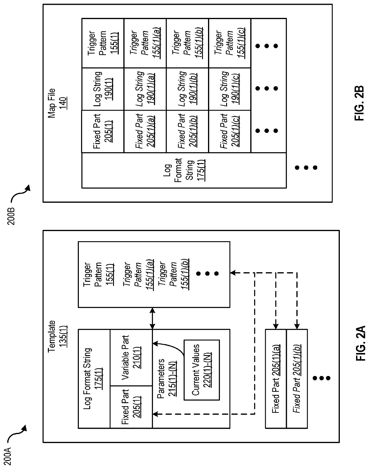
[0048]FIG. 2A is a block diagram 200A of a log modification tracking template that illustrates the contents of a log message that generates log lines, according to one embodiment. A template 135(1), which is a type of data structure, is maintained by log management server 105 and includes (the identities of) multiple log format strings and corresponding alert triggers. Template 135(1) also identifies, manages, and maintains modifications or changes to one or more portions of the log format strings (e.g., shown as fixed part 205(1)(a) and 205(1)(b) in FIG. 2A). For example, log format string 175(1) corresponds to alert trigger 155(1). Log format string 175(1), which is part of log statement 170(1), is typically composed of a fixed part 205(1), a variable part 210(1), and parameters 215(1)-(N) with current values 220(1)-(N). A fixed part of a log format string does not change the composition of a log line when a corresponding lo...
example implementation
[0065 of a Template, a Map File, and an Index
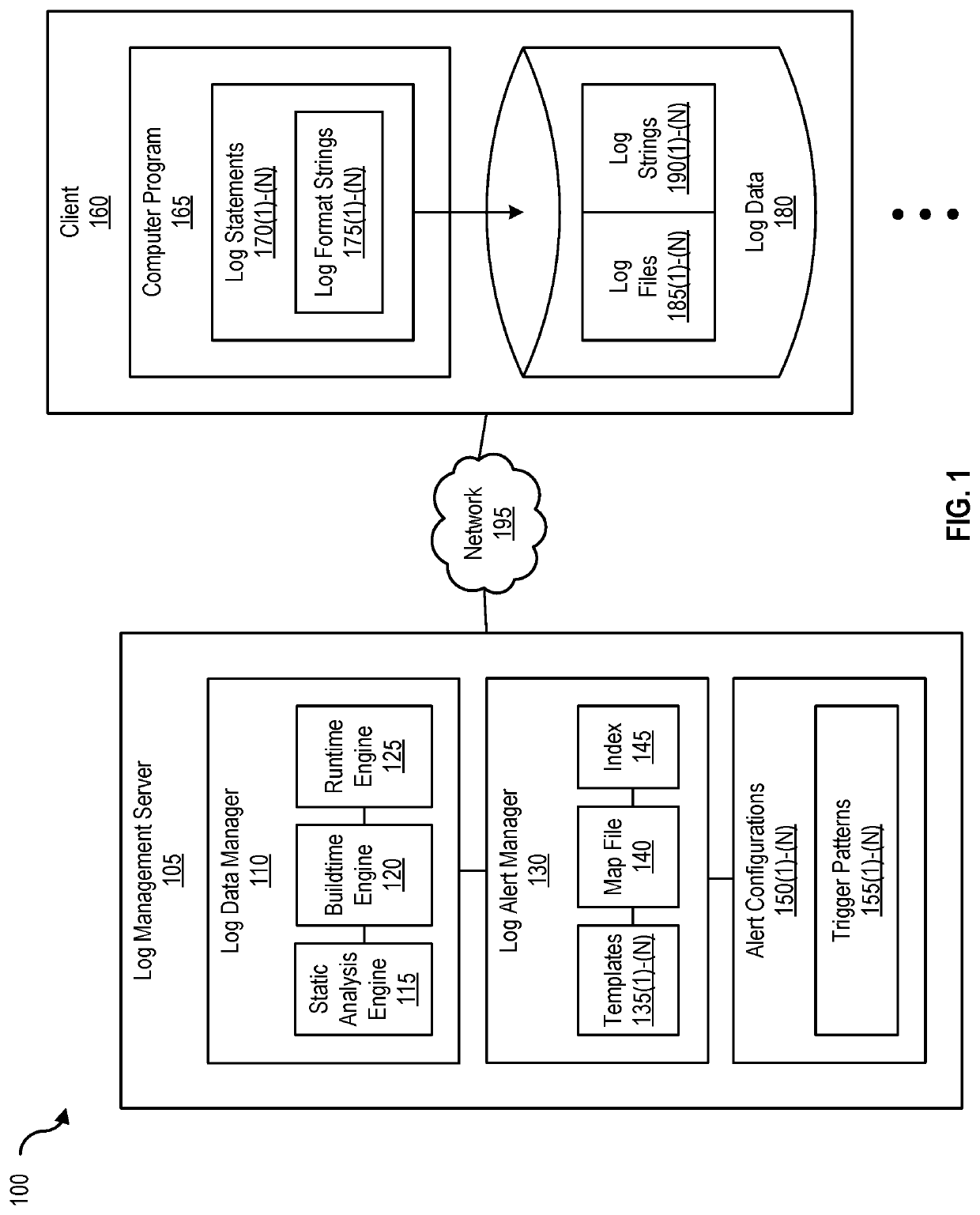
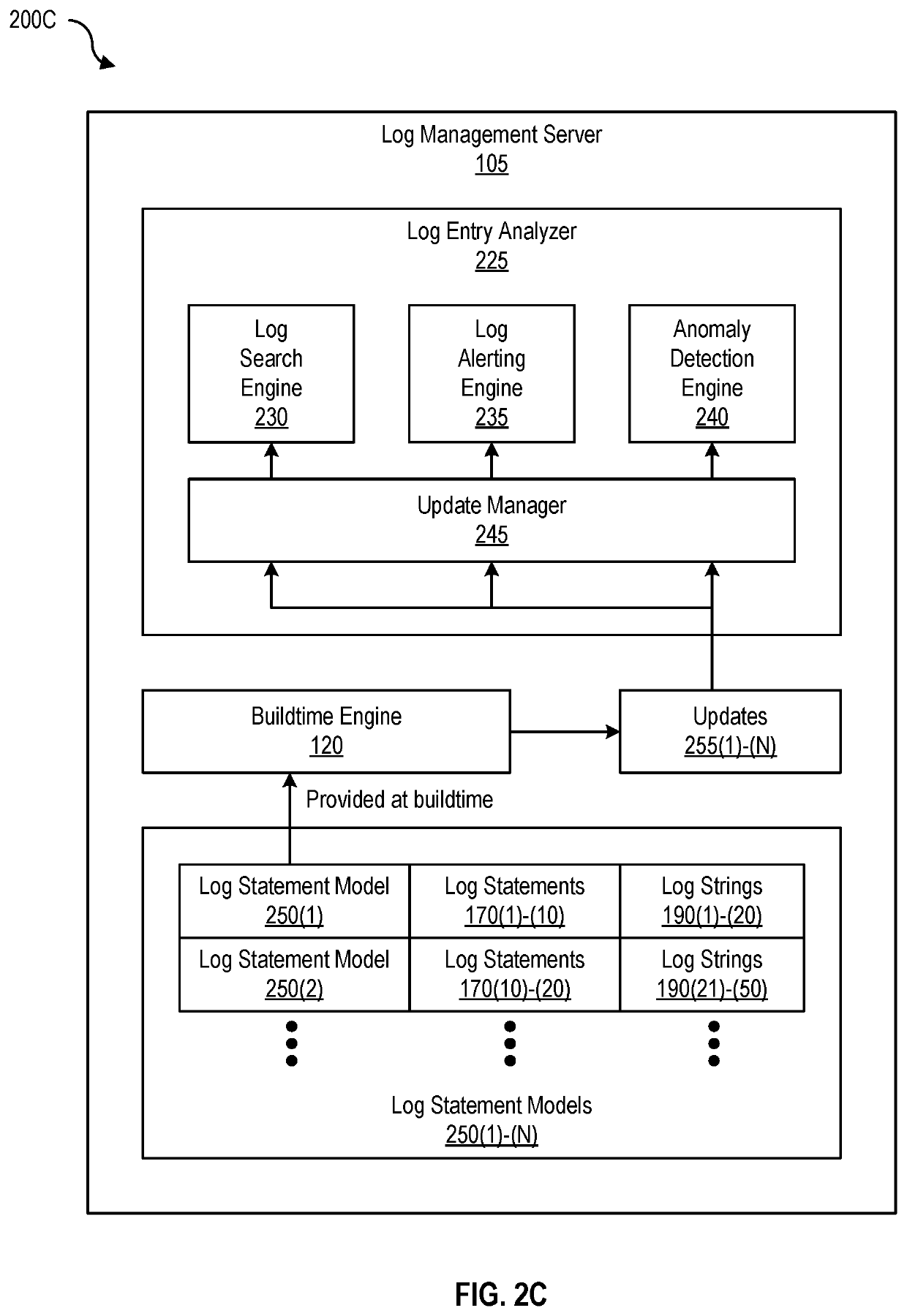
[0066]As shown in FIG. 1, log alert manager 130 of log management server 105 maintains templates 135(1)-(N), map file 140, and index 145. Templates 135(1)-(N) enumerate fixed parts, variable parts, and placeholders in log messages of log statements. As shown in FIG. 2C, log management server 105 also includes one or more models (e.g., log statement models 250(1)-(N)) that are generated based on one or more templates 135(1)-(N) of log statements (e.g., log statements 170(1)-(N)) that generates log lines (e.g., log strings 190(1)-(N)) and are provided during buildtime (e.g., to log entry analyzer 225 as shown in FIG. 2C).
[0067]Providing these log statement models to log entry analyzer 225 at buildtime permits log entry analyzer 225 to manage updates (e.g., updates 255(1)-(N)) to log search engine 230, log alerting engine 235, and anomaly detection engine 240 using update manager 245. Because modification of log statements causes mismatch be...
example networking
[0111 Environment
[0112]FIG. 9 is a block diagram of a networked system, illustrating how various computing devices can communicate via a network, according to one embodiment. Network 195 generally represents any type or form of computer network or architecture capable of facilitating communication between log management server 105, clients 160(1)-(N), developer system 190, and / or log management system 905. For example, network 195 can be a Wide Area Network (WAN) (e.g., the Internet) or a Local Area Network (LAN). In certain embodiments, a communication interface, such as communication interface 845 in FIG. 8, may be used to provide connectivity between log management server 105, clients 160(1)-(N), developer system 190, and / or log management system 905, and network 195.
[0113]In some embodiments, log data manager 110, log alert manager 130, and / or log entry analyzer 225 may be part of log management server 105 and / or log management system 905, or may be separate. All or a portion of...
PUM
 Abstract
Description
Claims
Application Information