
Gas monitoring image recording device, method, and program

Active Publication Date: 2021-08-26
KONICA MINOLTA INC
View PDF5 Cites 0 Cited by
  • Summary
  • Abstract
  • Description
  • Claims
  • Application Information

AI Technical Summary

Benefits of technology

The patent is about a device, method, and program for recording gas monitoring images. The aim is to make it easier to search for specific image data.

Problems solved by technology

However, because image data are usually obtained and stored continuously every day, an enormous amount of image data is accumulated, and thus it is difficult to find target materials (image data) from the enormous volume of image data.

Method used


Image

  • Gas monitoring image recording device, method, and program
  • Gas monitoring image recording device, method, and program
  • Gas monitoring image recording device, method, and program

Examples


Embodiment Construction

[0018]One or more embodiments of the present invention will now be described with reference to the drawings. However, the scope of the invention is not limited to the disclosed embodiments. It is to be noted that identical components are denoted by the same reference signs in drawings, and the description thereof is omitted as appropriate. In the present specification, components are collectively denoted by reference signs without suffixes, and are distinguished from each other by being denoted by reference signs with suffixes.

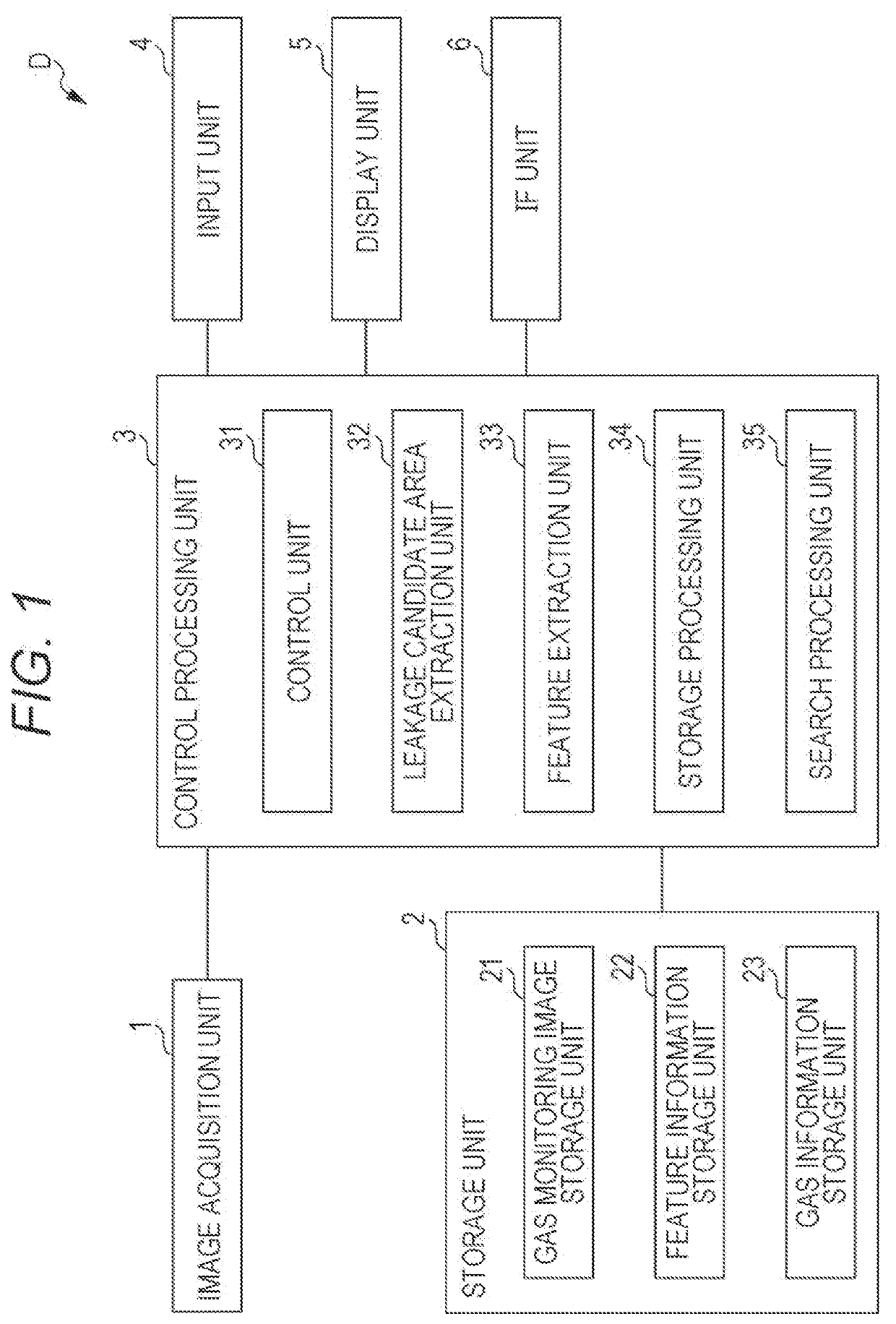
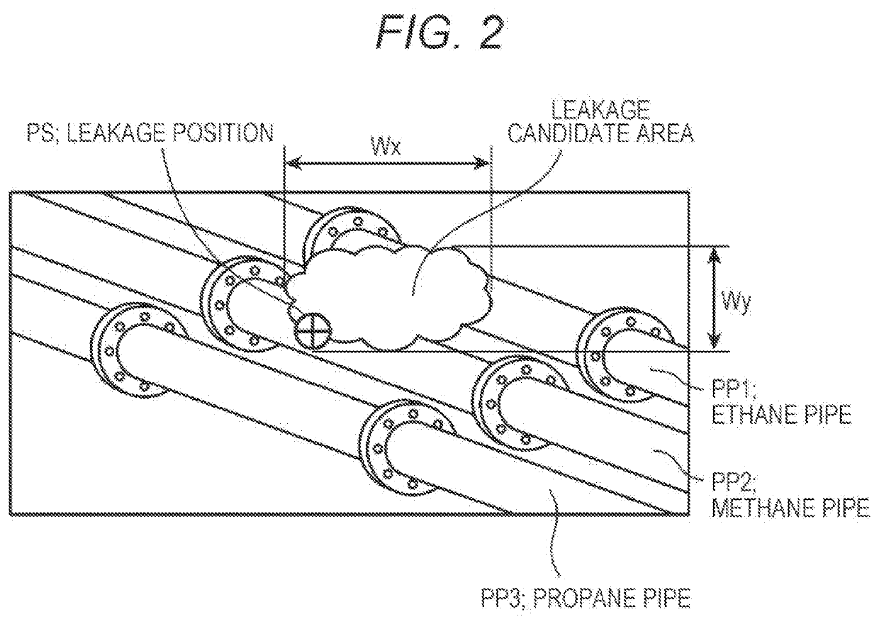
[0019]FIG. 1 is a block diagram illustrating a configuration of a gas monitoring image recording device according to an embodiment. FIG. 2 is a diagram for explaining features in the gas monitoring image recording device.

[0020]The gas monitoring image recording device according to the embodiment is a device that causes a storage unit to store, in a searchable manner, image data of gas monitoring images (gas monitoring image data) for use in monitoring a gas le...


PUM


Abstract

A gas monitoring image recording device, a gas monitoring image recording method, and a gas monitoring image recording program according to the present invention involve: acquiring gas monitoring image data including a plurality of time-series images for use in monitoring a gas leak; extracting a leakage candidate area as a candidate for a gas leak based on the gas monitoring image data acquired; extracting predetermined features related to the gas leak in response to extracting the leakage candidate area; and causing a storage unit to store the features extracted in association with the gas monitoring image data from which the leakage candidate area has been extracted.

Description

TECHNICAL FIELD[0001]The present invention relates to a gas monitoring image recording device, a gas monitoring image recording method, and a gas monitoring image recording program for recording a gas monitoring image for use in monitoring a gas leak.BACKGROUND ART[0002]Early action is required in the case of leakage of gas such as flammable gas, toxic gas, and organic solvent vapor from a pipe or a tank, for example. For this reason, devices that seek gas such as leaking gas have been researched and developed. One example of such devices is the gas leak detection device disclosed in Patent Literature 1.[0003]The gas leak detection device disclosed in Patent Literature 1 detects a gas leak in an inspection target area, and has an infrared camera that captures the inspection target area, an image processing unit that processes the infrared image captured by the infrared camera, and a gas leak determination unit that determines a gas leak based on the result of processing in the image...

Claims


Application Information

Patent Timeline
IPC IPC(8): G06T7/00G06K9/00G06K9/46G06T7/62G06T7/73G01M3/04G06V10/25
CPCG06T7/0004G06K9/00771G06K9/46G06T2207/10016G06T7/73G01M3/04G06T2207/30108G06T7/62G01M3/002G01M3/38G06F16/583G06V20/52G06V10/25
Inventor ZHANG, XIAOCHENKOTANI, SHOJI
Owner KONICA MINOLTA INC
Learn More