Low distortion flat diaphragm

a flat diaphragm, low distortion technology, applied in the field of electroacoustic, to achieve the effect of eliminating cutting oscillation and sound distortion and low distortion

Active Publication Date: 2022-11-08
CHEN GANG
View PDF2 Cites 0 Cited by
  • Summary
  • Abstract
  • Description
  • Claims
  • Application Information

AI Technical Summary

Benefits of technology

[0005]The utility model aims to provide a low distortion flat diaphragm which is expected to eliminate cutting oscillation and sound distortion generated by unbalanced distribution of mass of the diaphragm effectively in a locating and wiring way of improving the electric transduction coil.

Problems solved by technology

It is found by researches by the applicant that as the mass center of the conventional flat diaphragm is not matched with the mechanical center, cutting oscillation will be generated as a result of unbalanced distribution of the vibrating mass.
In addition, in the conventional flat diaphragm, locating and wiring of the electric transduction coil is designed to direct bestride the fixing region and the vibrating region to lead to too high rigidity of the fixing region and the vibrating region, thereby aggravating sound distortion of the flat vibrating diaphragm.

Method used


Image

  • Low distortion flat diaphragm
  • Low distortion flat diaphragm
  • Low distortion flat diaphragm

Examples


example 1

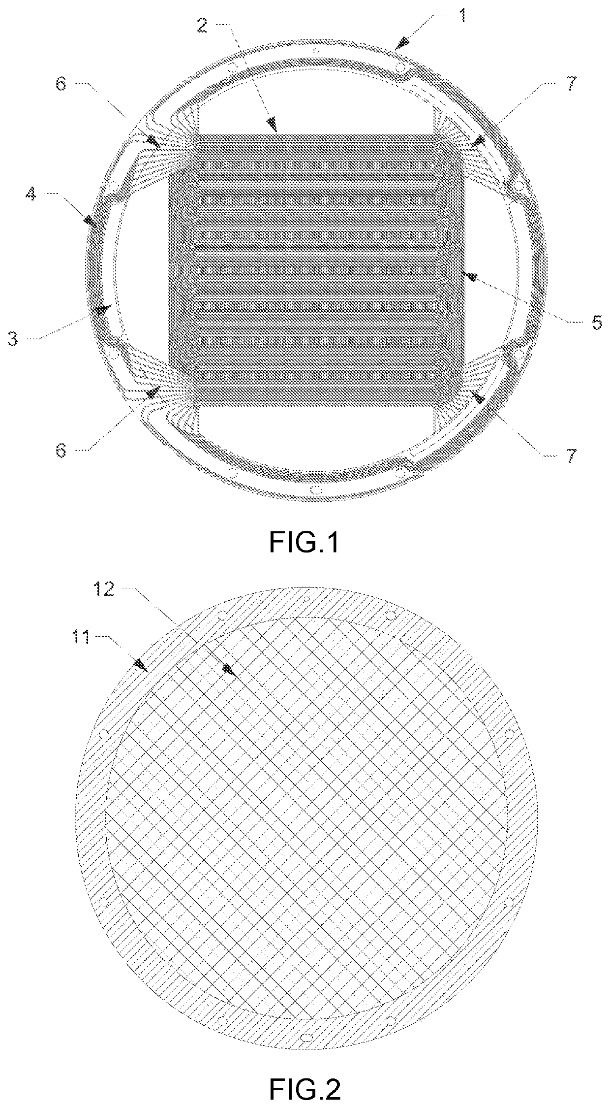
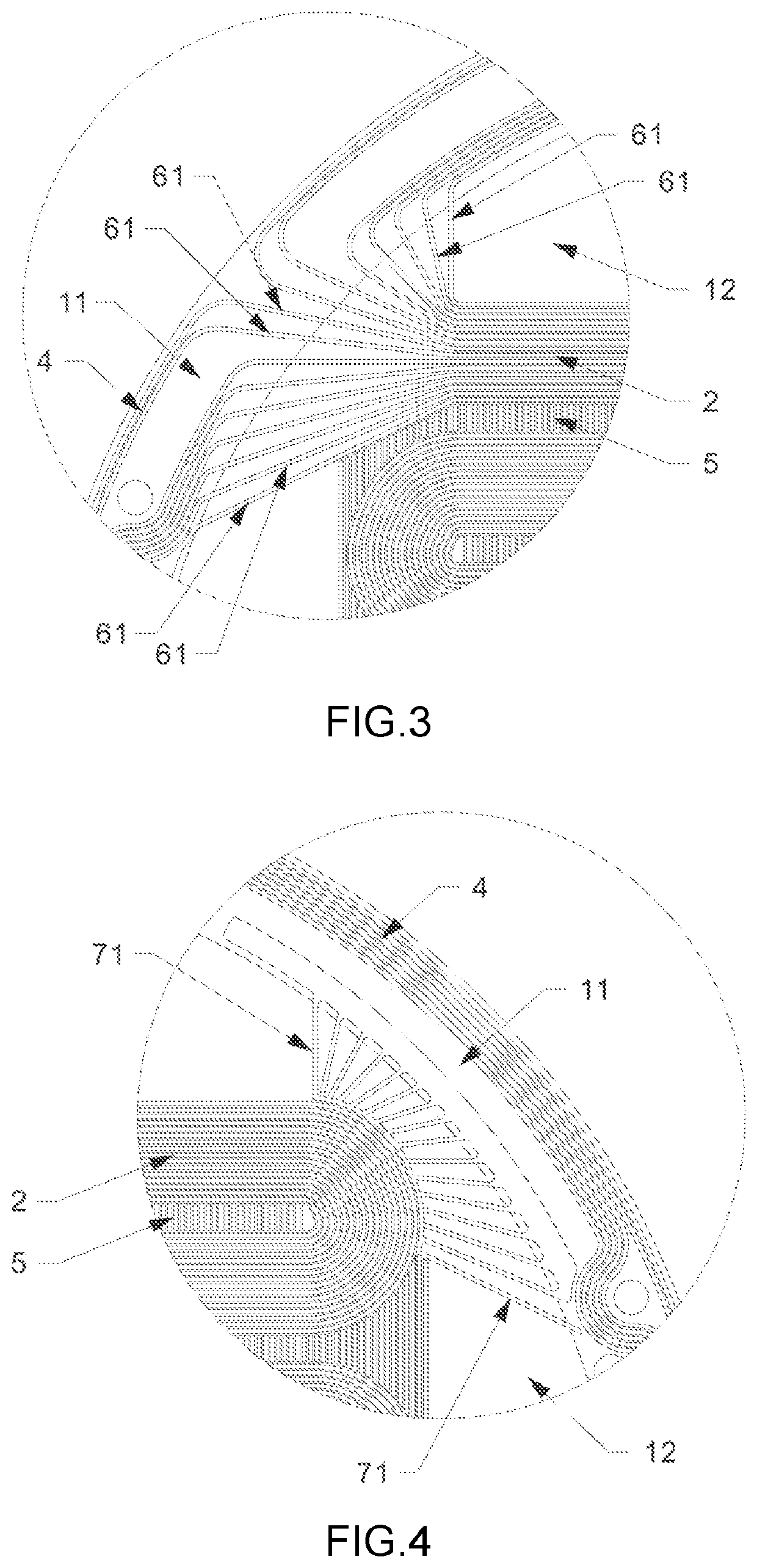
[0030]As shown in FIG. 1 to FIG. 4, in the embodiment, the contour of the diaphragm 1 is round.

[0031]In the embodiment, the electrical transduction coil 2, the coil terminal 3 and the coil locating and wiring 4 are designed on the diaphragm 1, and the fan-out leads 61 of the fan-out line 6 are adjusted to be diffused to the fixing region 11 in a fan shape from the vibrating region 12; the brim compliant balancing lines 7 are designed on the diaphragm 1, the brim compliant balancing lines 7 and fan-out lines 6 are symmetrically arranged in an X shape relative to a center axis of the diaphragm 1; and with reference to the magnetic field configured by the flat vibrating diaphragm, the mass balancing line 5 on the diaphragm 1 is designed according to a dimension of a magnetic path.

[0032]In the embodiment, the coil conductor of the electrical transduction coil 2 is designed with narrow linewidth, such that each coil conductor of the electrical transduction coil is connected with one fan-...

example ii

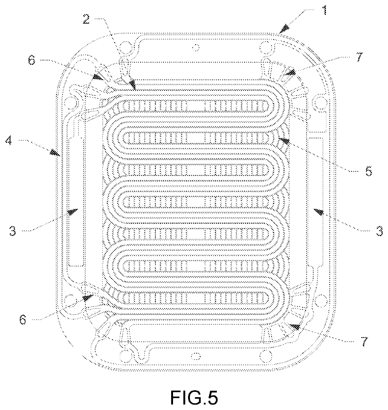
[0033]As shown in FIG. 5 to FIG. 8, in the embodiment, the contour of the diaphragm 1 is rectangular.

[0034]In the embodiment, the electrical transduction coil 2, the coil terminal 3 and the coil locating and wiring 4 are designed on the diaphragm 1, and the fan-out leads 61 of the fan-out line 6 are adjusted to be diffused to the fixing region 11 in a fan shape from the vibrating region 12; the brim compliant balancing lines 7 are designed on the diaphragm 1, the brim compliant balancing lines 7 and fan-out lines 6 are symmetrically arranged in an X shape relative to a center axis of the diaphragm 1; and with reference to the magnetic field configured by the flat vibrating diaphragm, the mass balancing line 5 on the diaphragm 1 is designed according to a dimension of a magnetic path.

[0035]In the embodiment, the coil conductor of the electrical transduction coil 2 is designed with narrow linewidth. If each coil conductor of the electrical transduction coil is connected with one fan-o...


PUM


Abstract

A low distortion flat diaphragm provided with a diaphragm. A periphery of the diaphragm is defined as a fixing region and a middle portion thereof is defined as a vibrating region. The diaphragm is provided with an electric transduction coil located in the vibrating region, and a coil terminal and coil locating and wiring located in the fixing region. The diaphragm is further provided with a mass balancing line that makes a mass center of the vibrating region be matched with a mechanical center. The diaphragm is further provided with two brim compliant balancing lines. The brim compliant balancing lines and fan-out lines are symmetrically arranged in an X shape relative to a center axis of the diaphragm. The utility model eliminates cutting oscillation and sound distortion generated by unbalanced distribution of mass of the diaphragm effectively in a locating and wiring way of improving the electric transduction coil.

Description

BACKGROUND OF THE INVENTION[0001]The utility model relates to the electroacoustic technical field, and in particular discloses a low distortion flat diaphragm.[0002]In the electroacoustic technical field, a flat loudspeaker (also referred as to an isomagnetic loudspeaker) gains its name due to an adopted transduction structure. A flat vibrating diaphragm is provided with an annular bracket and a flat diaphragm compounded on the bracket. The periphery of the flat diaphragm is defined as a fixing region combined with the bracket and the middle portion thereof is defined as a vibrating region where the electrical transduction coil is arranged. The flat vibrating diaphragm is placed in a magnetic field. After the audio signal is connected to the electrical transduction coil, the electrical transduction coil drives the flat diaphragm to move synchronously in the magnetic field as the audio signal changes, such that air is vibrated to generate a sound.[0003]As far as the flat diaphragm is...

Claims


Application Information

Patent Timeline
Patent Type & Authority Patents(United States)
IPC IPC(8): H04R7/04
CPCH04R7/04H04R9/047
Inventor CHEN, GANG
Owner CHEN GANG
Why Eureka
Try Eureka