Three dimensional (3D) imaging using optical coherence factor (OCF)

a three-dimensional imaging and optical coherence factor technology, applied in image enhancement, image analysis, instruments, etc., can solve the problems of complex algorithms, inefficient 3d imaging methods, and ambiguities in the height profile reconstruction, so as to achieve the effect of simple algorithms, multiple 2d image frames, and simple 3d imaging methods

Active Publication Date: 2022-11-22
CALIFORNIA INST OF TECH
View PDF4 Cites 0 Cited by
  • Summary
  • Abstract
  • Description
  • Claims
  • Application Information

AI Technical Summary

Problems solved by technology

For topographic scenarios, this type of 3D imaging methods are generally inefficient as the inherent information in such scenes are much more constrained and lower in magnitude.
However, there will be ambiguities in the r

Method used


Image

  • Three dimensional (3D) imaging using optical coherence factor (OCF)
  • Three dimensional (3D) imaging using optical coherence factor (OCF)
  • Three dimensional (3D) imaging using optical coherence factor (OCF)

Examples


example

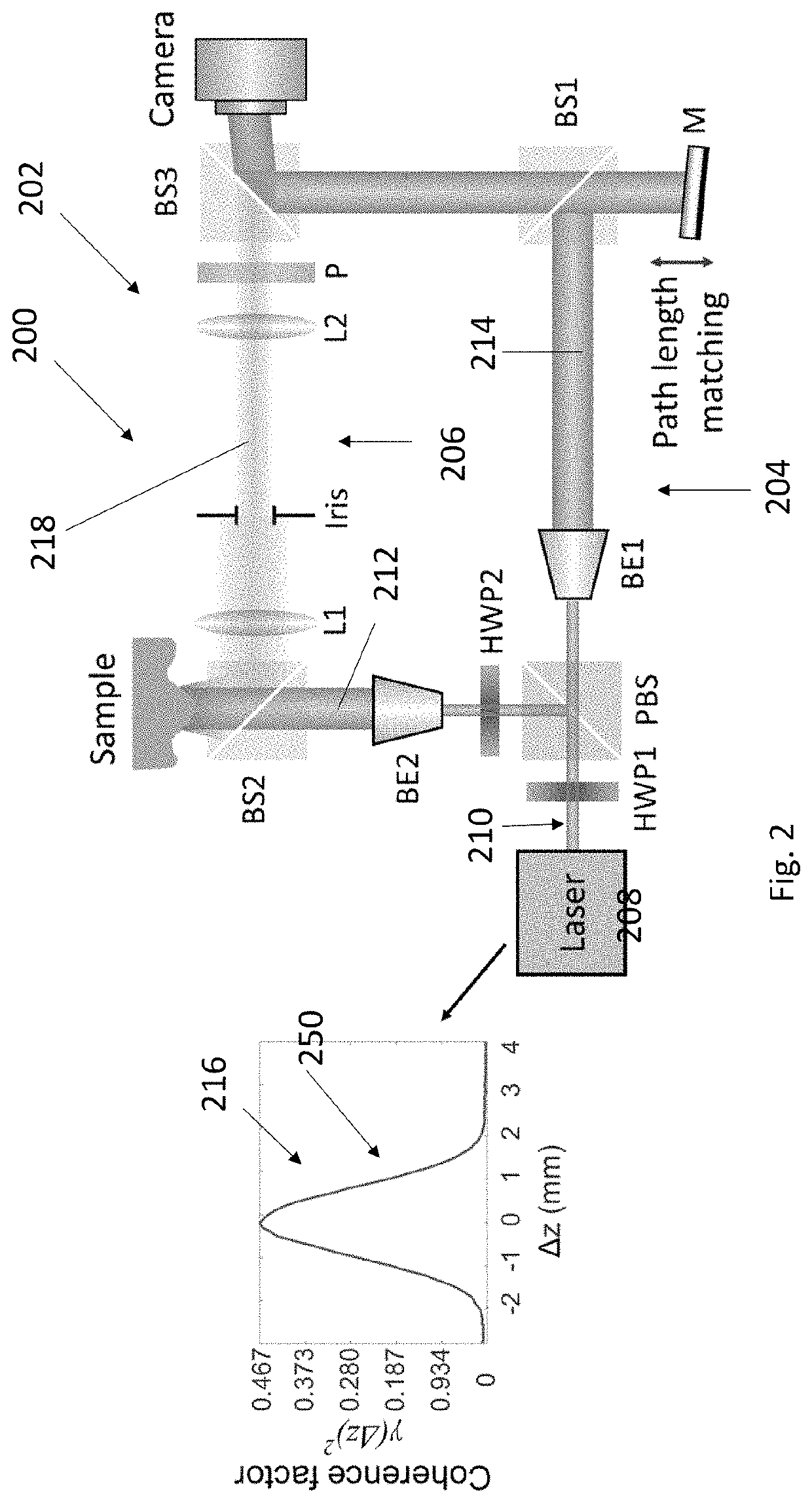
[0051]An example experimental setup of OCF is shown in FIG. 2. The laser beam (532 nm, 150 mW, CrystaLaser Inc. USA) is first split into two arms by a polarizing beam splitter (PBS). Light on arm R1 serves as the reference beam and light on arm R2 illuminates the sample. The sample is imaged onto the camera (GX1920, Allied Vision) by a 4-f system. A tilted plane wave (R1) is added on the camera by BS3 and interferes with light from arm R1, creating an off-axis hologram on the camera. We perform pathlength difference adjustments on R1 such that 1) the pathlength difference between the two arms is in the monotonic region of the laser coherence profile, and 2) the whole scene in DoF interferes with the reference beam. The coherence factor is retrieved from the hologram by using off-axis holography [11]. The coherence profile of the laser was characterized before imaging experiments. To measure the coherence profile, we put a mirror as the sample, and axially scanned the reference mirro...


PUM


Abstract

A 3-D imaging system including a computer determining a plurality of coherence factors measuring an intensity contrast between a first intensity of a first region of an interference comprising constructive interference between a sample wavefront and a reference wavefront, and a second intensity of a second region of the interference comprising destructive interference between the sample wavefront and the reference wavefront, wherein the interference between a reference wavefront and a reflection from different locations on a surface of an object. From the coherence factors, the computer determines height data comprising heights of the surface with respect to an x-y plane perpendicular to the heights and as a function of the locations in the x-y plane. The height data is useful for generating a three dimensional topological image of the surface.

Description

CROSS REFERENCE TO RELATED APPLICATIONS[0001]This application claims the benefit under 35 U.S.C. Section 119(e) of and commonly-assigned U.S. Provisional Patent Application Ser. No. 62 / 941,221, filed on Nov. 27, 2019, by Jian Xu and Changhuei Yang, entitled “3D Imaging using optical coherence factor (OCF),” (CIT-8400); which application is incorporated by reference herein.BACKGROUND OF THE INVENTION1. Field of the Invention[0002]The present disclosure relates to imaging systems and methods of imaging.Description of the Related Art[0003](Note: This application references a number of different publications as indicated throughout the specification by one or more reference numbers within brackets, e.g., [x]. A list of these different publications ordered according to these reference numbers can be found below in the section entitled “References.” Each of these publications is incorporated by reference herein.)[0004]Since real world objects are three dimensional (3D) in nature while com...

Claims


Application Information

Patent Timeline
IPC IPC(8): G01B11/06G06T11/00G01B9/02
CPCG01B11/0608G01B9/02043G06T11/005G06T2207/10101G06T11/006G01B11/2441G01B9/0209G01B9/02084G01B9/02083G06T2211/456
Inventor XU, JIANYANG, CHANGHUEI
Owner CALIFORNIA INST OF TECH
Why Eureka
Try Eureka