Dielectric waveguide resonator, dielectric waveguide filter, and method of adjusting the characteristics thereof

a technology of dielectric filters and dielectric resonators, applied in the direction of resonators, gas discharge lamps, climate sustainability, etc., can solve the problems of difficult to connect a prism-shaped dielectric to a metallic case, and difficult to achieve the effect of adjusting the characteristics of the filter

Inactive Publication Date: 2001-04-26
MURATA MFG CO LTD
View PDF0 Cites 37 Cited by
  • Summary
  • Abstract
  • Description
  • Claims
  • Application Information

AI Technical Summary

Problems solved by technology

However, these dielectric resonators have problems in design and production arising from their structure.
In the case of the TM110-mode dielectric resonator, it is not easy to connect a prism-shaped dielectric to a metallic case or a case covered with a conducting film through which a current flows.
When the prism-shaped dielectric and the outer conductor are combined in an integral fashion, a complicated and difficult molding technique is required.
This causes an increase in the cost of the production and assembly process.
Since

Method used


Image

  • Dielectric waveguide resonator, dielectric waveguide filter, and method of adjusting the characteristics thereof
  • Dielectric waveguide resonator, dielectric waveguide filter, and method of adjusting the characteristics thereof
  • Dielectric waveguide resonator, dielectric waveguide filter, and method of adjusting the characteristics thereof

Examples


Embodiment Construction

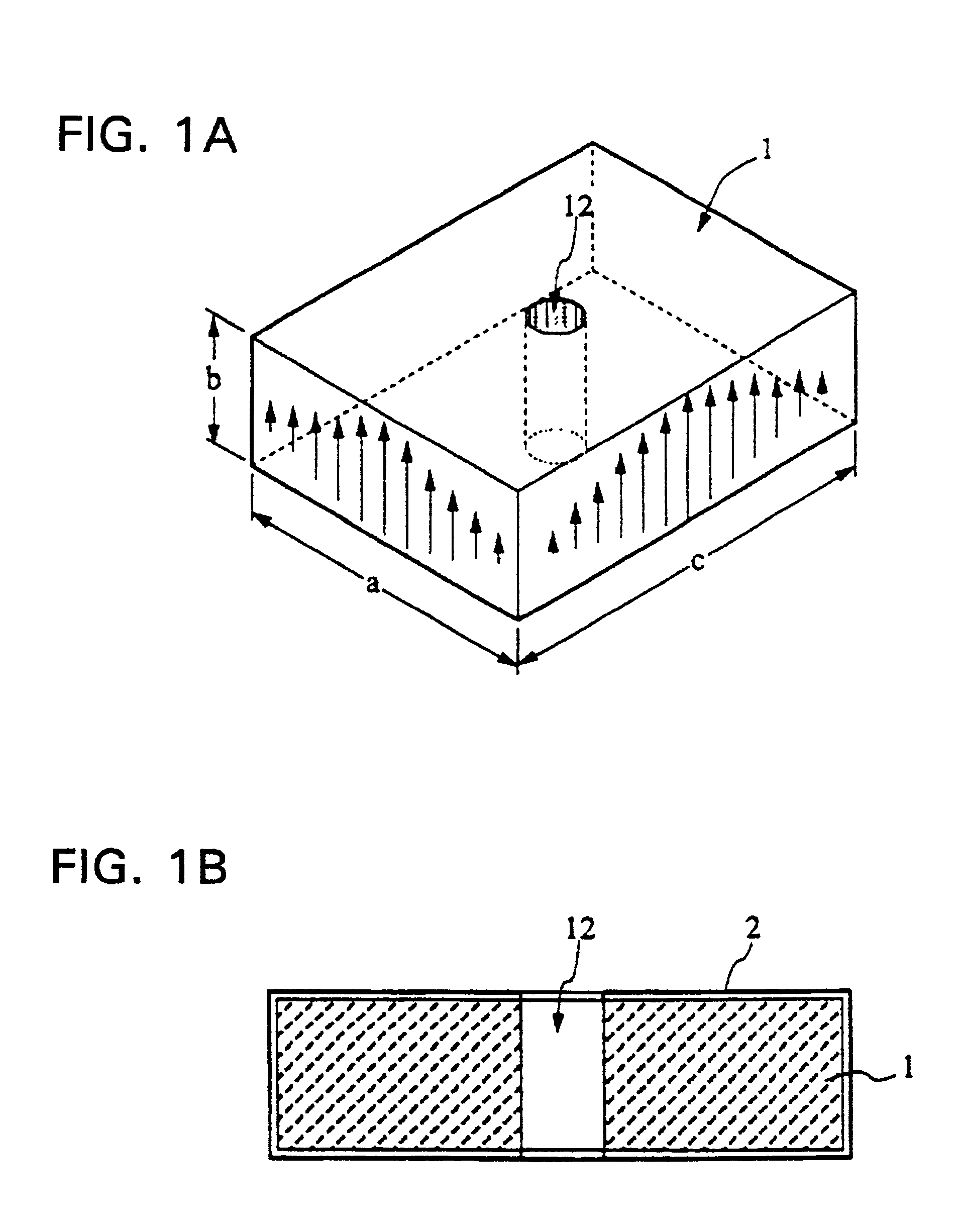
64. FIGS. 1A and 1B illustrate the construction of a dielectric waveguide resonator (hereinafter referred to simply as a dielectric resonator) according to a 1st embodiment of the present invention, wherein FIG. 1A is a perspective view illustrating its external appearance and FIG. 1B is a cross-sectional view thereof. Reference numeral 1 denotes a dielectric block in a substantially rectangular form. A circular through-hole 12 is formed in the center of the dielectric block 1 and a conducting film 2 is formed on the outer surface (six side faces) of the dielectric block 1. In FIG. 1A, the arrows drawn on the sides of the dielectric block 1 represent the projections of the electric field distribution inside the dielectric block 1 (in the central portion or near the central portion) onto the two sides of the dielectric block 1. The actual internal electric field distribution is similar to that shown in FIG. 31 wherein the energy of electric field in the vertical direction in the figu...


PUM


Abstract

A conducting film is formed on a dielectric block in a dielectric waveguide resonator, and a through-hole is formed in the dielectric block. The unloaded Q is set by selecting the outside dimensions of the dielectric block. The resonance frequency is set by selecting the size and location of the through-hole as well as the outside dimensions of the dielectric block. A terminal electrode is formed on the outer surface of the dielectric block. A coupling hole is formed in the dielectric block and a coupling electrode is formed on the inner surface of the coupling hole. One end of the coupling electrode is connected to the terminal electrode and the other end of the coupling electrode is either connected to the conducting film formed on the outer surface of the dielectric block or terminated inside the dielectric block. The above structure allows an increase in the degree of freedom in the design of the characteristics including the resonance frequency and unloaded Q of the dielectric waveguide resonator. The invention also provides a dielectric waveguide filter with a simple coupling mechanism whereby it is possible to couple to an external circuit without having to use an additional member and without electromagnetic leakage.

Description

1. This is a division of Ser. No. 09 / 464,154 filed Dec. 16, 1999, allowed, which is a division of Ser. No. 08 / 871,333 filed Jun. 9, 1997, now U.S. Pat. No. 6,020,800, the disclosures of which are incorporated by reference herein.2. 1. Field of the Invention3. The present invention relates to a dielectric waveguide resonator and a dielectric waveguide filter for use particularly in a microwave or millimeter wave range, and to a method of adjusting the characteristics thereof.4. 2. Description of the Related Art5. There are various types of dielectric resonators known for use in the microwave range. They include: a TE01.delta.-mode dielectric resonator consisting of a dielectric in the form of a solid circular cylinder or a hollow circular cylinder placed in a shield case; a TM110-mode dielectric resonator consisting of a prism-shaped dielectric which is placed in a metallic case or a case covered with a conducting film in such a manner that the dielectric extends from the upper to th...

Claims


Application Information

Patent Timeline
IPC IPC(8): H01P1/207H01P1/205H01P1/208H01P7/04H01P7/06H01P7/10
CPCH01P1/2056H01P1/2088H01P7/04H01P7/06H01P7/10Y02B20/22Y02B20/00
Inventor ARAKAWA, SHIGEJITSUNODA, KIKUO
Owner MURATA MFG CO LTD
Why Eureka
Try Eureka