Condition analyzer

a condition analyzer and analyzer technology, applied in the field of condition analyzers, can solve problems such as the condition of the machine to deteriora

Inactive Publication Date: 2001-05-10
SPM INSTR
View PDF0 Cites 26 Cited by
  • Summary
  • Abstract
  • Description
  • Claims
  • Application Information

AI Technical Summary

Problems solved by technology

2. Machines with moving parts are subject to wear with the passage of time, which often causes the condition of the machine to deteriorate.

Method used


Image

  • Condition analyzer
  • Condition analyzer

Examples


Embodiment Construction

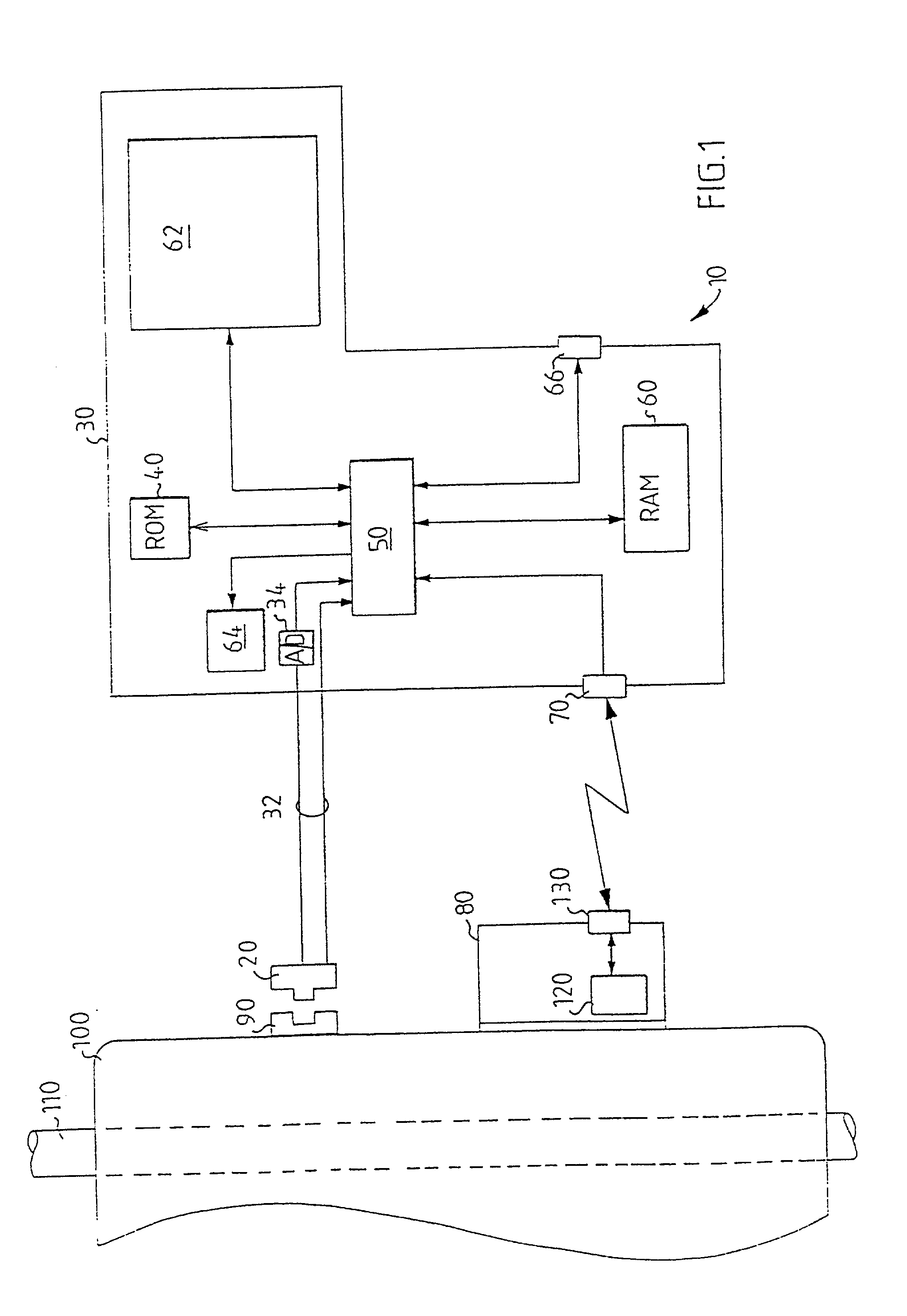
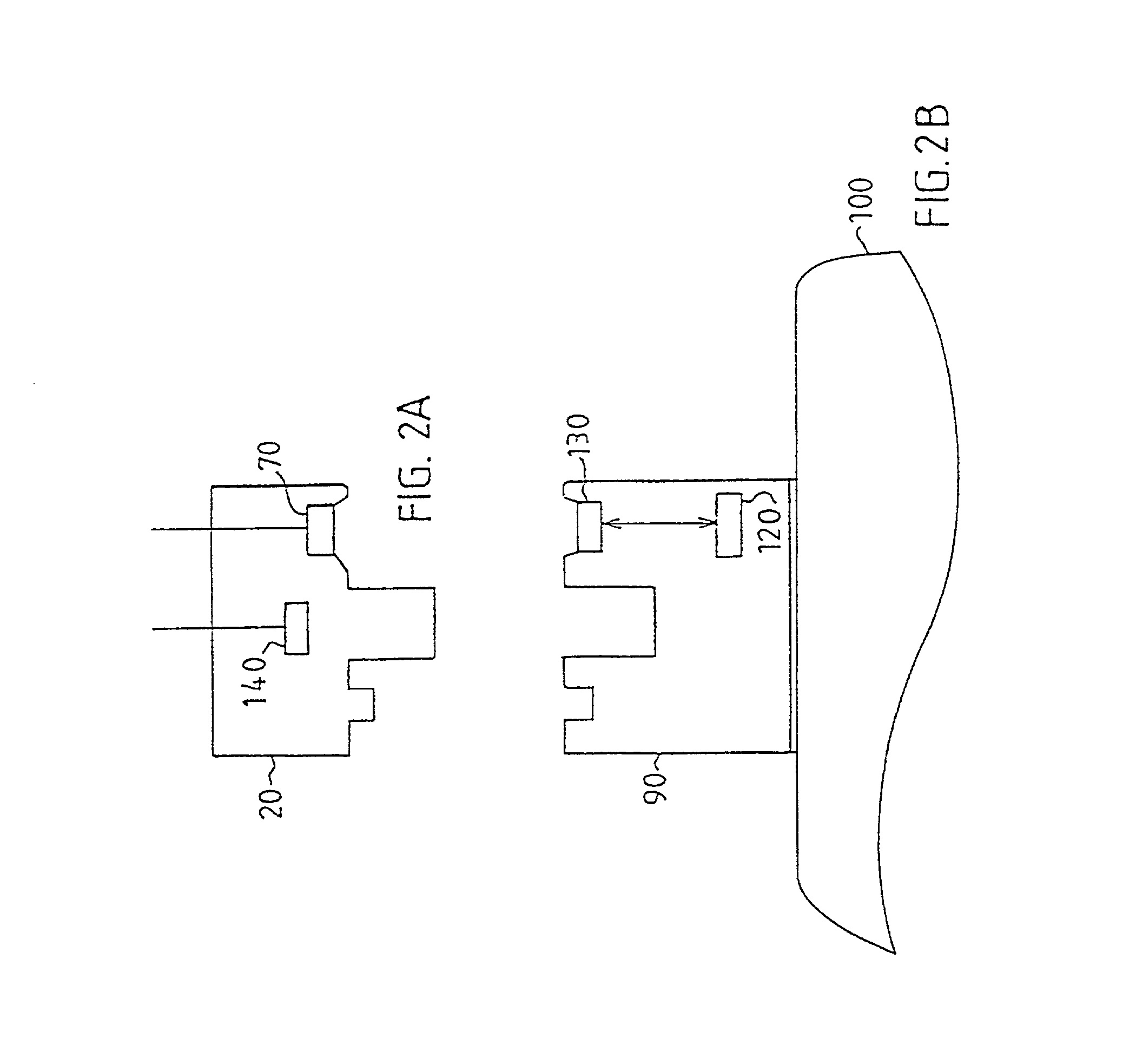
17. FIG. 1 shows a schematic block diagram of an embodiment of a condition analyzing system 10 according to the invention. The condition analyzing system comprises a sensor unit 20 for producing a measured value dependent on movement and, more precisely, dependent on vibrations.

18. The sensor unit 20 is connected to an analysis apparatus 30 via a conductor 32. The analysis apparatus 30 comprises a non-volatile memory 40, a microprocessor 50 and a read / write memory 60. A computer program is stored in the read memory 40, and by means of this computer program the function of the analysis apparatus 30 is controlled. When it is written below that the microprocessor 50 performs a certain function, it shall be understood that the microprocessor runs a certain part of the program which is stored in the memory 40.

19. The microprocessor 50 is connected to a display unit 62. By means of the display unit 62 a user of the condition analyzing system is informed of the condition of the current mea...


PUM


Abstract

The invention relates to a method for evaluating the condition of a machine (100) with a measuring point (90), which method is performed by a movable analysis apparatus (30). The method comprises the steps of producing a condition value, by means of measuring at the measuring point, which condition value is dependent on the actual condition of the machine, and storing the condition value in a writable information carrier (120) which is placed by, or in the vicinity of, the measuring point (90) so that the condition value subsequently can be used as a reference condition value. The invention further relates to an apparatus for performing the method and a device for co-operating with the analysis apparatus and for mounting by a measuring point on the machine (100).

Description

1. The present invention relates to a method for generating a condition value for a measuring point on a machine having a measuring point, and a system for performing the method.STATE OF THE ART2. Machines with moving parts are subject to wear with the passage of time, which often causes the condition of the machine to deteriorate. Examples of such machines with movable parts are motors, pumps, generators, compressors, lathes and CNC-machines. It is known to, more or less regularly, investigate the operating condition of such machines. The operating condition can be determined by measuring the amplitude of vibrations in the bearings and by measuring temperature changes on the casing of the machine, which temperatures are dependent on the operating condition of the bearing. Such condition checks of machines with rotating or other moving parts are of great significance for safety and also for the length of the life of such machines. It is known to perform such measurements on machines...

Claims


Application Information

Patent Timeline
Patent Type & Authority Applications(United States)
IPC IPC(8): G01D18/00G01M13/00G01H1/00G07C3/00
CPCG01D18/008G01H1/003G07C3/00
Inventor ARONSSON, CARSTEN
Owner SPM INSTR
Why Eureka
Try Eureka