
Wavefront sensor, and lens meter and active optical reflecting telescope using the same

a technology of wavefront sensor and active optical reflection, which is applied in the direction of optical elements, instruments, optical radiation measurement, etc., can solve the problems of reducing the sensitivity to displacement, blurring of the luminous point of the area sensor, and significant reduction of the s/n ratio

Inactive Publication Date: 2001-07-05
KK TOPCON
View PDF0 Cites 13 Cited by
  • Summary
  • Abstract
  • Description
  • Claims
  • Application Information

AI Technical Summary

Problems solved by technology

The conventional wavefront sensor has a problem however that when the incident light beam is a plane wave, the S / N ratio can be sufficiently improved by using a single focus lens and an area sensor located at the focal point of the single focus lens, however, if the incident light beam is not a plane wave, the luminous point on the area sensor becomes blurred and the S / N ratio decreases significantly.
However, in the former case, for an incident light other than the plane wave, the displacement of the luminous point becomes small, lowering the sensitivity to the displacement.
Thus, the accuracy of the measurement of wavefront shape is deteriorated in both cases.

Method used


Image

  • Wavefront sensor, and lens meter and active optical reflecting telescope using the same
  • Wavefront sensor, and lens meter and active optical reflecting telescope using the same
  • Wavefront sensor, and lens meter and active optical reflecting telescope using the same

Examples


Embodiment Construction

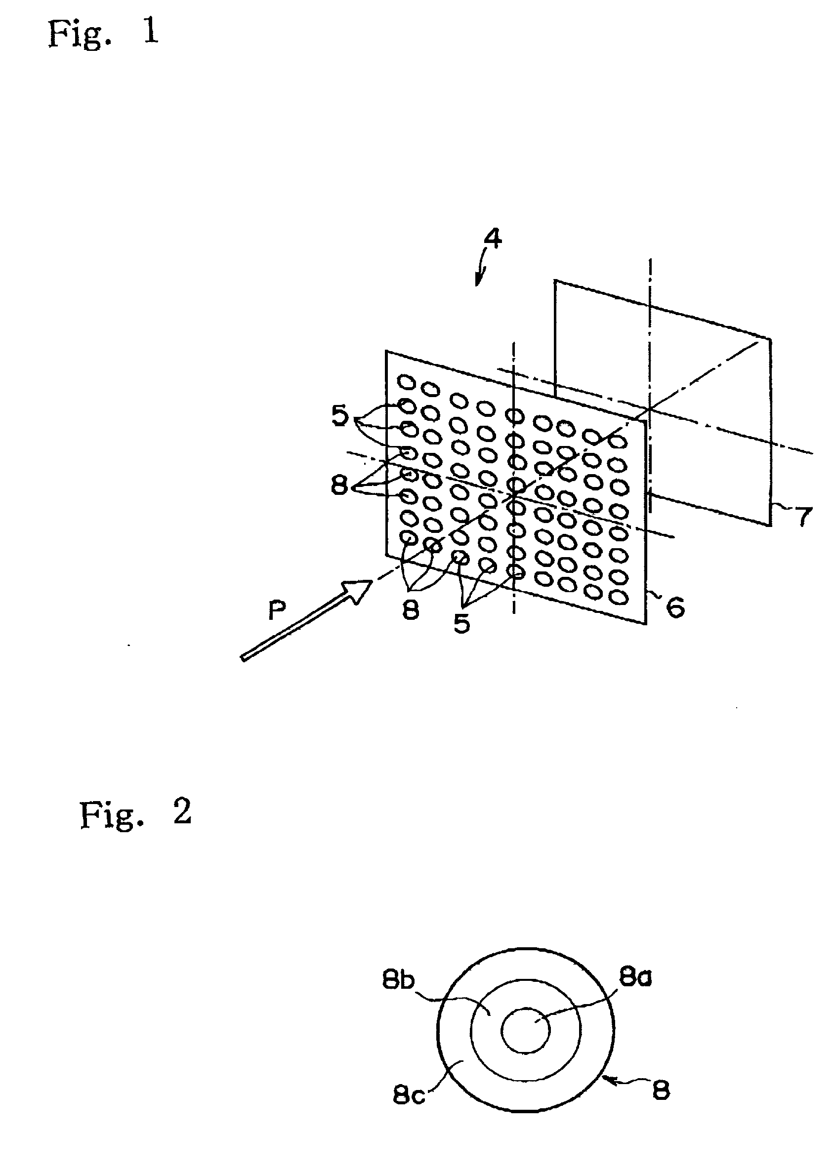
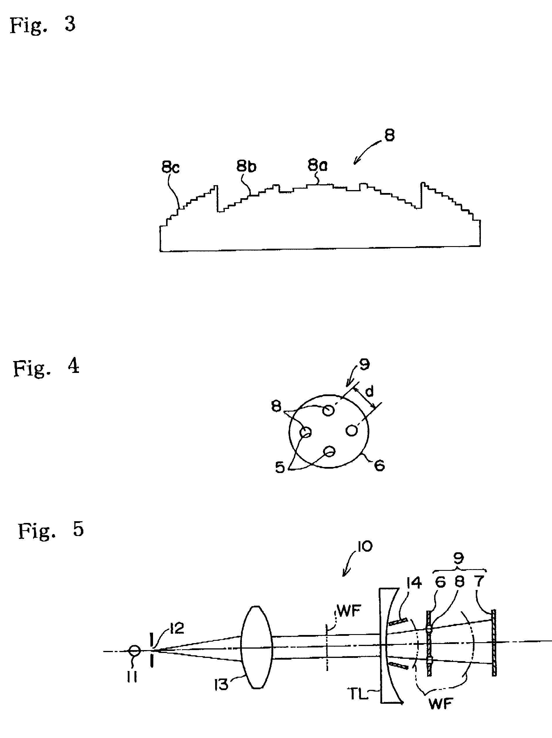
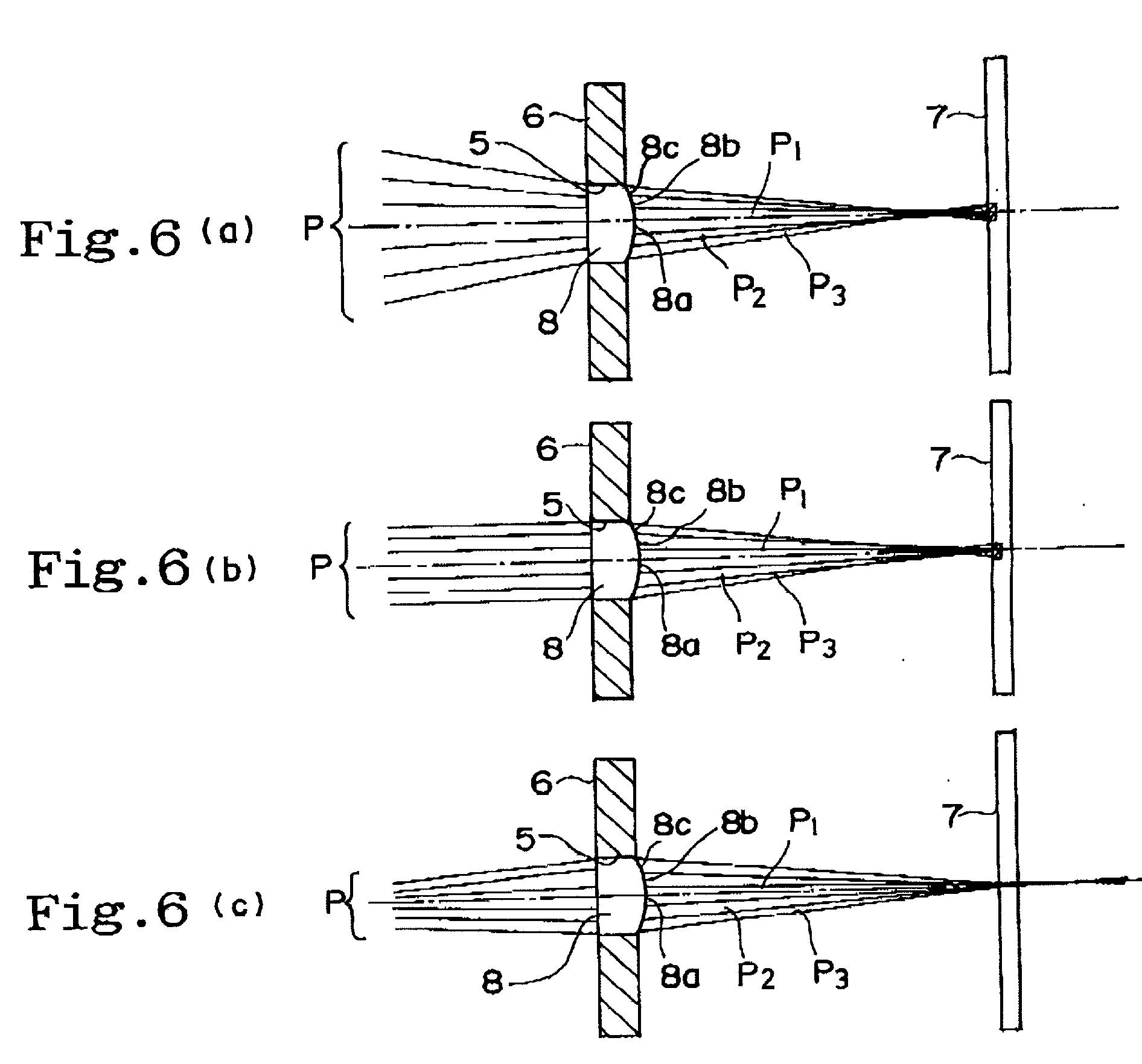
[0048] In the comparative example, the conventional wavefront sensor shown in FIGS. 12(a)-12(c) is used in the lens meter 10 in place of the wavefront sensor 9. The Hartmann plate 1 and area sensor 3 of the conventional wavefront sensor are similar to the Hartmann plate 6 and area sensor 7, respectively, of the wavefront sensor 9 but differ therefrom in that the lenses 2 used in the Hartmann plate 1 comprise a single focus lens.

[0049] In the case where the refracting power of the tested lens TL is approximately 0 D, because a wavefront similar to the plane wave is incident to the Hartmann plate 1, the pinhole 12 forming a point light source focuses the light on the area sensor 3 and forms a clear or sharp luminous point Q1 (FIG. 12(a)). In this instance, since the luminous point Q1 has high luminous energy (as indicated by the solid line shown in FIG. 13) and excels in S / N ratio, the position of luminous point Q1 can be detected with high accuracy. In addition, any scars or contamin...


PUM


Abstract

A wavefront sensor includes a plurality of lenses disposed in the same plane, and an area sensor that receives a bundle of rays of light collected through each of the lenses as a luminous point. Each of the lenses comprises a plurality of concentric areas with different focal lengths, and the area sensor is located substantially halfway between a first position in which a plane wave forms an image after passing through one of the concentric areas with a minimum focal length, and a second position in which the plane wave forms an image after passing through another area with a maximum focal length. With the wavefront sensor thus arranged, the measurement can be always achieved with high accuracy without involving noticeable blurring of luminous points on the area sensor regardless of the wavefront shape of a light beam incident to the lenses.

Description

[0001] 1. Field of the Invention[0002] The present invention relates to a wavefront sensor for measuring wavefront shape of a light beam, and a lens meter and an active optical reflecting telescope using the wavefront sensor.[0003] 2. Description of Related Art[0004] Conventionally, a Hartmann wavefront sensor is known as a wavefront sensor for measuring wavefront shape of a light beam. The Hartmann wavefront sensor includes a plate member called the Hartmann plate having multiple small openings regularly formed therein at a constant interval, and an area sensor disposed parallel to the Hartmann plate. A light beam is radiated onto the Hartmann plate from the opposite side of the area sensor. The incident light beam forms a thin pencil or bundle of rays of light as it passes through the openings and creates multiple luminous points on the area sensor according to the number of openings.[0005] When the incident light beam is a plane wave, the interval between the openings in the Hart...

Claims


Application Information

Patent Timeline
Patent Type & Authority Applications(United States)
IPC IPC(8): G01J9/00G02B27/00
CPCG01J9/00G02B27/00
Inventor YANAGI, EIICHIFUJINO, MAKOTO
Owner KK TOPCON
Learn More