Self-centering timing disk hub and method of mounting the same

a timing disk and hub technology, applied in the direction of transmission system, bearing/suspension of measurement apparatus, controlling members, etc., can solve the problems of shaft distortion, cost pressure in mass production, and difficulty in maintaining the required tolerance in production

Inactive Publication Date: 2001-07-05
PWB RUHLATEC INDPROD
View PDF0 Cites 6 Cited by
  • Summary
  • Abstract
  • Description
  • Claims
  • Application Information

AI Technical Summary

Problems solved by technology

With current state-of-the-art devices, a distortion tended to occur when the shaft is inserted into the timing disk hub, since the hub which is pushed onto the finish-machined shaft, has a reduced diameter.
The stringent requirements on the surface quality of the motor shaft and the timing disk hub as well as the tight manufacturing tolerances create a cost pressure in mass production.
It is also difficult to maintain the required tolerances in production.
A slight displacement of the timing disk relative to the motor shaft can adversely affect the operation of, for example, servo motors.
Since during installation this does not produce a press-fit, only a relatively small force is required.

Method used


Image

  • Self-centering timing disk hub and method of mounting the same
  • Self-centering timing disk hub and method of mounting the same
  • Self-centering timing disk hub and method of mounting the same

Examples


Embodiment Construction

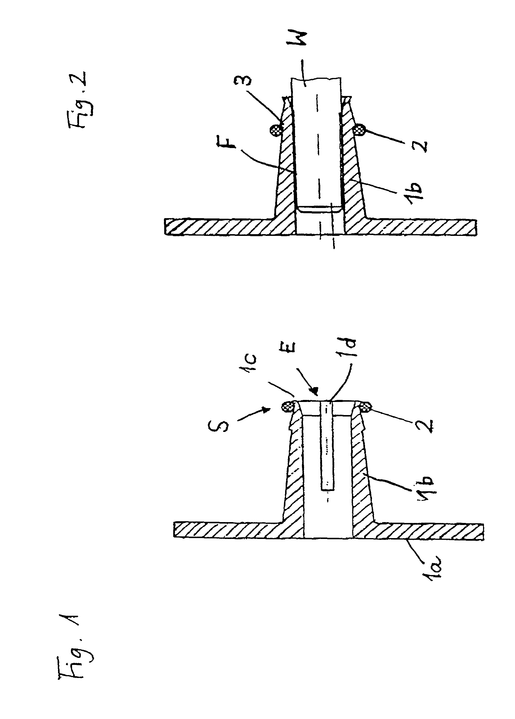
[0020] FIG. 1 shows a cross-sectional view of a timing disk hub according to the invention with a timing disk support surface 1a and a tubular hub sleeve 1b. As seen from FIG. 1, the outer wall surface of the hub sleeve 1b has a conical form, with the cone angle opening from the sleeve end E to the timing disk support surface 1a. Slots 1d are formed in the hub sleeve which extend into the contact region with the motor shaft W (FIG. 2).

[0021] A stop face 1c which reliably secures a clamping element S in the rest position before installation, is formed at the end of the hub sleeve 1b. The clamping element S preferably includes a clamping ring 2 which in its rest position is not pre-tensioned, but is placed loosely on the outer wall surface of the sleeve end.

[0022] FIG. 2 shows a timing disk hub according to the invention after installation on the motor shaft W. As seen in FIG. 2, the clamping ring 2 has moved to a tensioning position on the conical outer wall surface of the hub sleeve...


PUM


Abstract

The invention relates to a self-centering timing disk hub with a timing disk support surface and a tubular hub sleeve, wherein the end of the hub sleeve can be pushed onto a motor shaft so as to provide in the hub sleeve a contact surface between the inner wall surface of the hub sleeve and the motor shaft. The outer wall surface of the hub sleeve has an at least approximately conical form, wherein the cone angle opens from the sleeve end to the timing disk support surface. The hub sleeve is slotted at least in the region of the motor shaft and a clamping element is movably arranged on the outer wall surface at the sleeve end. The invention also relates to a method for mounting a self-centering timing disk hub on a shaft, in particular a motor shaft of an encoder.

Description

[0001] 1. Field of the Invention[0002] The present invention relates to a self-centering timing disk hub with a timing disk support surface (1a) and a tubular hub sleeve (1b) and to a method for mounting the same on a motor shaft.[0003] 2. Description of the Related Art[0004] Self-centering timing disks of the afore described type are known from DE 196 41 929 A1 (RUHLATEC Industrieprodukte GmbH). The timing disk hub described therein is installed in an encoder which is connected with a motor by a simple rotational motion.[0005] Sufficient clearance should be provided for centering the timing disk hub on the motor shaft during installation. For this reason, the end of the timing disk hub facing the motor has a pilot bore for aligning the vertical axes of the shaft and the timing disk. With current state-of-the-art devices, a distortion tended to occur when the shaft is inserted into the timing disk hub, since the hub which is pushed onto the finish-machined shaft, has a reduced diame...

Claims


Application Information

Patent Timeline
Patent Type & Authority Applications(United States)
IPC IPC(8): G01D5/245F16B9/02F16D1/08F16D1/091F16D1/095G01D11/02G05G1/02H03M1/00
CPCF16D1/0858F16D1/095G01D11/02G05G1/02
Inventor BRAUN, PAUL-WILHELM
Owner PWB RUHLATEC INDPROD
Why Eureka
Try Eureka