Display apparatus capable of adjusting subfield number according to brightness

Inactive Publication Date: 2001-07-05
PANASONIC CORP
View PDF0 Cites 22 Cited by
  • Summary
  • Abstract
  • Description
  • Claims
  • Application Information

AI Technical Summary

Benefits of technology

0041] According to a preferred embodiment, the apparatus further comprises image characteristic determining means, which generates the multiplication factor A based on brightness data, and multiplying means, which amplifies a picture signal A times based on multiplication factor A, and increases multiplication factor A as the average level (Lav) of said brightness decreases.
0042] According to a preferred embodiment, the apparatus further comprises image characteristic determining means, which generates a weighting multiplier N based on brightness data, and increases a multiplication result of multiplication factor A and weighting multiplier N as the average level (Lav) of said brightness decreases.
0043] According to a preferred embodiment, the apparatus further comprises image characteristic determining means, which generates a weighting

Problems solved by technology

(1996)-286636 (corresponds to specification in U.S. Pat. No. 5,757,343), but here, only light emission frequency and gain control

Method used


Image

  • Display apparatus capable of adjusting subfield number according to brightness
  • Display apparatus capable of adjusting subfield number according to brightness
  • Display apparatus capable of adjusting subfield number according to brightness

Examples


first embodiment

[0097] First Embodiment

[0098] FIG. 11 shows a block diagram of a first embodiment of a display apparatus capable of adjusting the subfield number in accordance with brightness. Input 2 receives R, G, B signals. A vertical synchronizing signal, horizontal synchronizing signal are inputted to a timing pulse generator 6 from input terminals VD, HD, respectively. An A / D converter 8 receives R, G, B signals and performs A / D conversion. A / D converted R. G, B signals undergo reverse gamma correction via a reverse gamma correction device 10. Prior to reverse gamma correction, the level of each of the R, G, B signals, from a minimum 0 to a maximum 255, is displayed in 1 pitch in accordance with an 8-bit signal as 256 linearly different levels (0, 1, 2, 3, 4, 5, . . . , 255). Following reverse gamma correction, the levels of the R, G, B signals, from a minimum 0 to a maximum 255, are each displayed with an accuracy of roughly 0.004 in accordance with a 16-bit signal as 256 non-linearly differ...

second embodiment

[0131] Second Embodiment

[0132] FIG. 14 shows a block diagram of a display apparatus of a second embodiment. This embodiment, relative to the embodiment in FIG. 11, further provides a contrast detector 50 parallel to an average level detector 28. The image characteristic determining device 30 determines the 4 parameters on the basis of image contrast in addition to the peak level Lpk and average level Lav, or in place thereof. For example, when contrast is intense, this embodiment can decrease the multiplication factor A.

third embodiment

[0133] Third Embodiment

[0134] FIG. 15 shows a block diagram of a display apparatus of a third embodiment. This embodiment, relative to the embodiment in FIG. 11, further provides an ambient illumination detector 52. The ambient illumination detector 52 receives a signal from ambient illumination 53, outputs a signal corresponding to ambient illumination, and applies this signal to the image characteristic determining device 30. The image characteristic determining device 30 determines the 4 parameters on the basis of ambient illumination in addition to the peak level Lpk and average level Lav, or in place thereof. For example, when ambient illumination is dark, this embodiment can decrease the multiplication factor A, or the weighting multiplier N.


PUM


Abstract

A display apparatus adjusts the brightness of a plasma display panel. The display apparatus comprises an adjusting device, which acquires image brightness data, and adjusts the number of subfields Z on the basis of brightness data.

Description

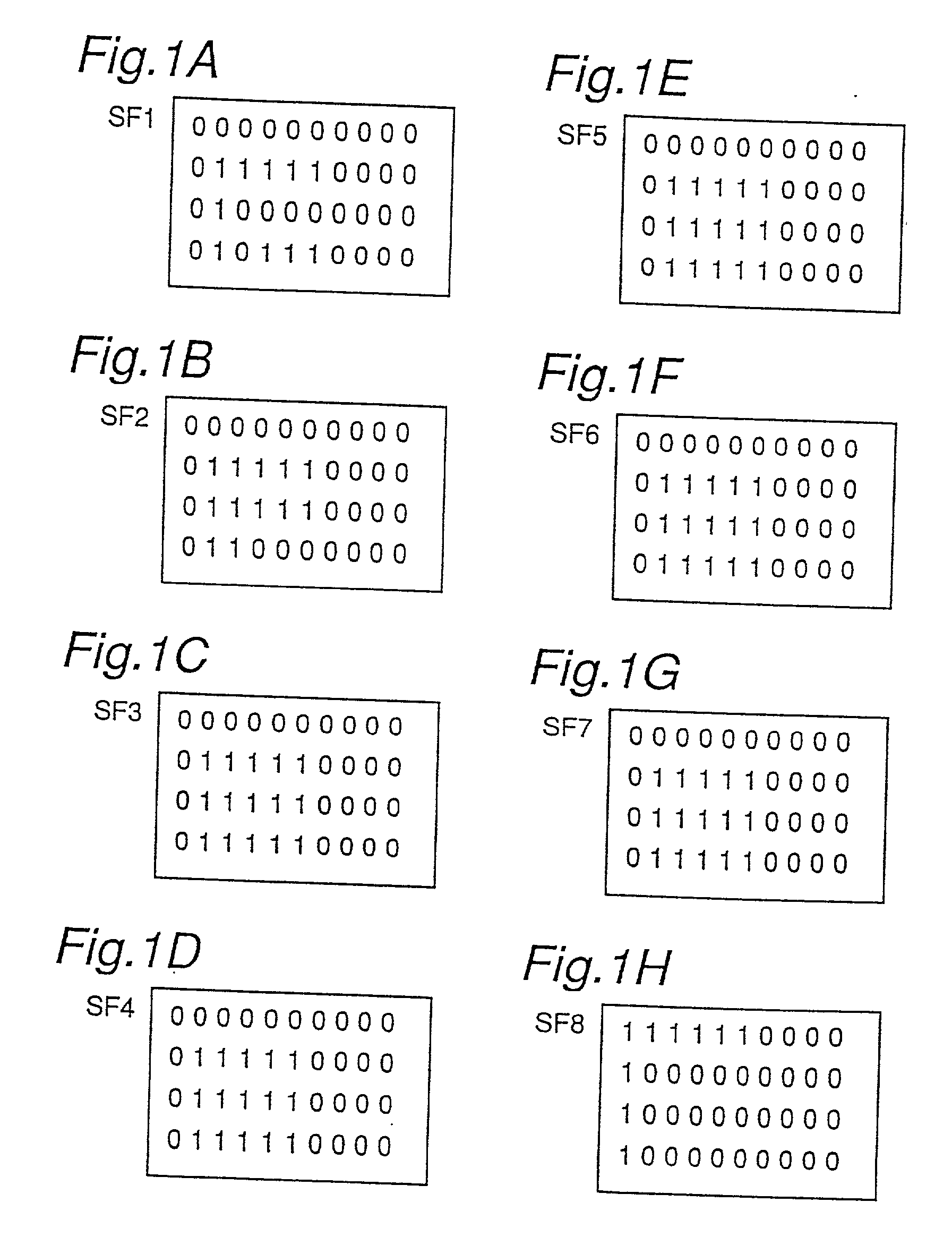
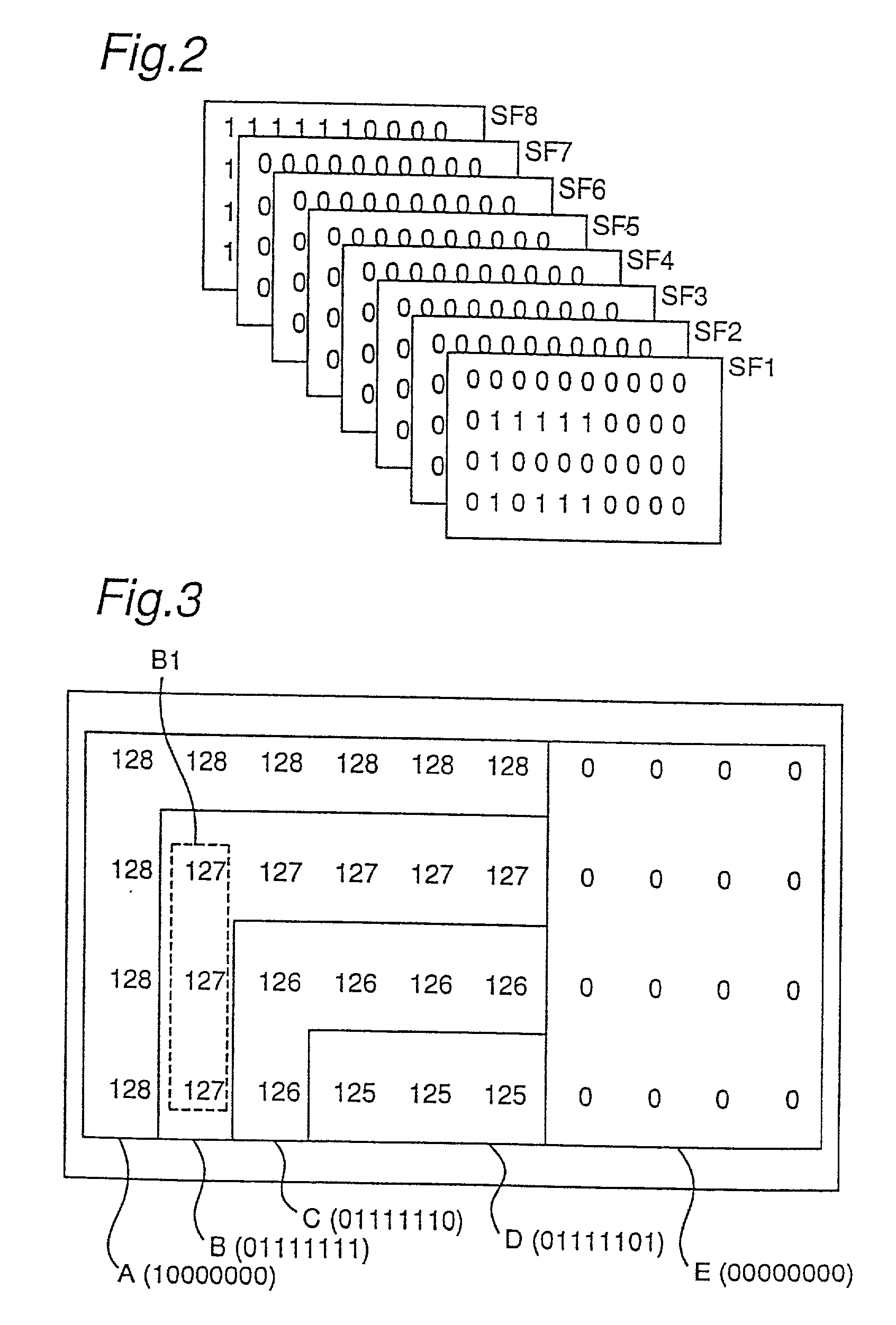
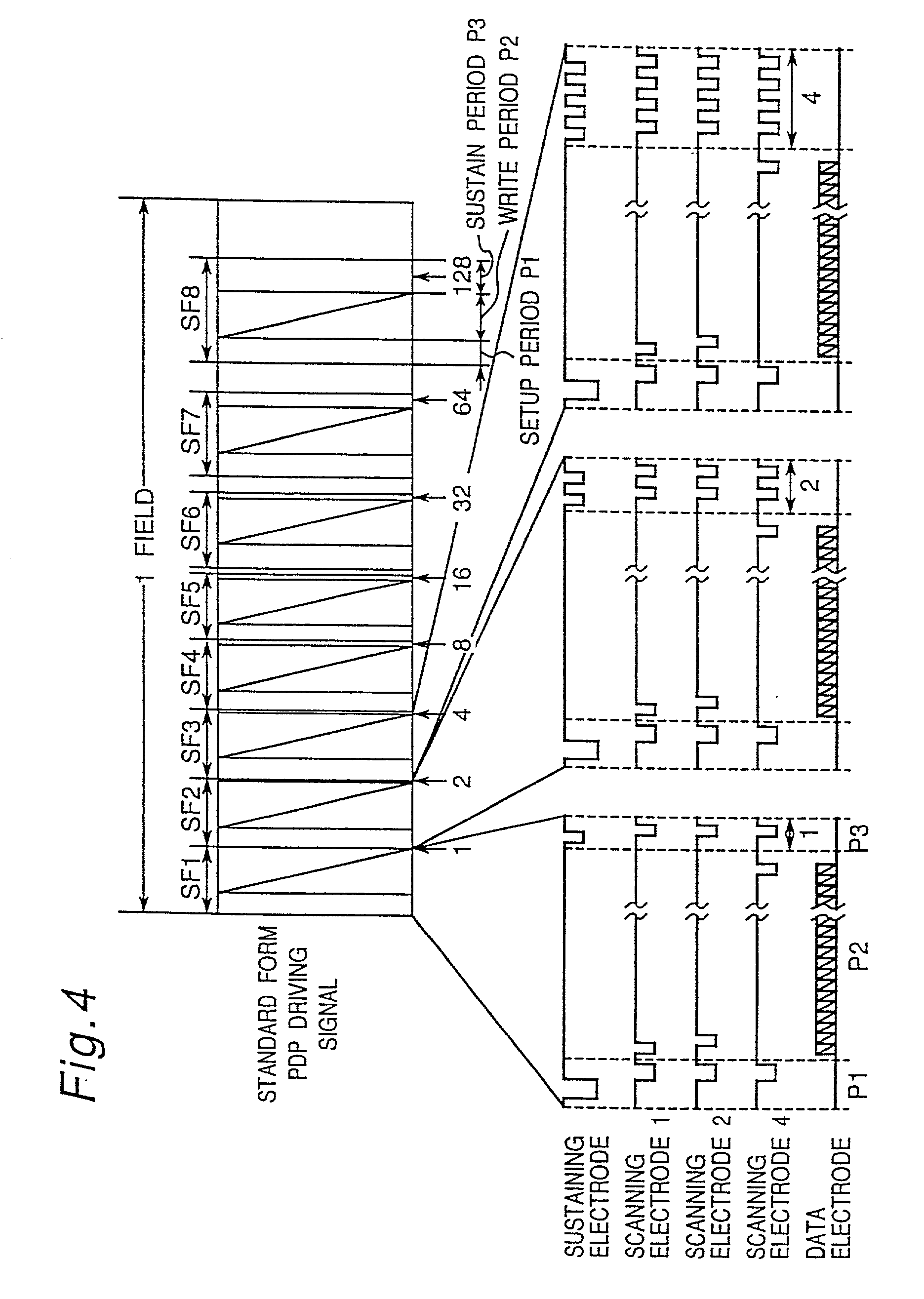
[0001] This is a divisional of U.S. application Ser. No. 09 / 355,341, filed Aug. 5, 1999 which was the National Stage of International Application No. PCT / JP98 / 05510, filed Dec. 7, 1998, the contents of which are expressly incorporated by reference herein in their entireties. The International Application was published in English.DESCRIPTION[0002] 1. Technical Field[0003] The present invention relates to a display apparatus of a plasma display panel (PDP) and digital micromirror device (DMD), and more specifically, to a display apparatus capable of adjusting a subfield number in accordance with brightness.[0004] 2. Background Art[0005] A display apparatus of a PDP and a DMD makes use of a subfield method, which has binary memory, and which displays a dynamic image possessing half tones by temporally superimposing a plurality of binary images that have each been weighted. The following explanation deals with PDP, but applies equally to DMD as well.[0006] A PDP subfield method is expla...

Claims


Application Information

Patent Timeline
IPC IPC(8): G09G3/291G09G3/20G09G3/28G09G3/294G09G3/296G09G3/34
CPCG09G3/2022G09G3/2033G09G3/2037G09G3/2803G09G3/34G09G2320/0261G09G2320/0266G09G2320/0276G09G2320/041G09G2320/0626G09G2320/106G09G2330/021G09G2360/144G09G2360/16G09G3/294G09G3/291G09G3/296
Inventor KASAHARA, MITSUHIROISHIKAWA, YUICHIMORITA, TOMOKO
Owner PANASONIC CORP
Why Eureka
Try Eureka