Eureka AIR delivers breakthrough ideas for toughest innovation challenges, trusted by R&D personnel around the world.

Method and system for controlling an air mass flow in an aircraft

Inactive Publication Date: 2001-07-12
AIRBUS OPERATIONS GMBH
View PDF0 Cites 15 Cited by
  • Summary
  • Abstract
  • Description
  • Claims
  • Application Information

AI Technical Summary

Benefits of technology

0024] Thus, various types of sensors and/or measuring devices are used in combination according to the invention such as temperature sensors, pressure sensors, air volume flow sensors and altitude sensors. These sensors are connected with their outputs to the data acquisition section of the closed loop control unit or to a performance characteristics updating circuit. The data acquisition section processes the respective sensor information or data to provide respective actual flow volume signals to one input of the comparator. These flow volume signals represent actual performance characteristics of the above mentioned network elements under the actual current pressure, temperature and altitude conditions. The computer section for correcting or updating rated performance characteristics stored in the memory provides updated performance characteristic values or data for comparing with the actual performance characteristic values or data to produce closed loop control signals that will correct the operation of the controllable air flow c

Problems solved by technology

However, these conventional controls are subject to air mass flow deviations that conventionally have not been corrected.
However, such a control does not take into account that in an aircraft the overall cabin pressure is variable.

Method used


Image

  • Method and system for controlling an air mass flow in an aircraft

Examples


Embodiment Construction

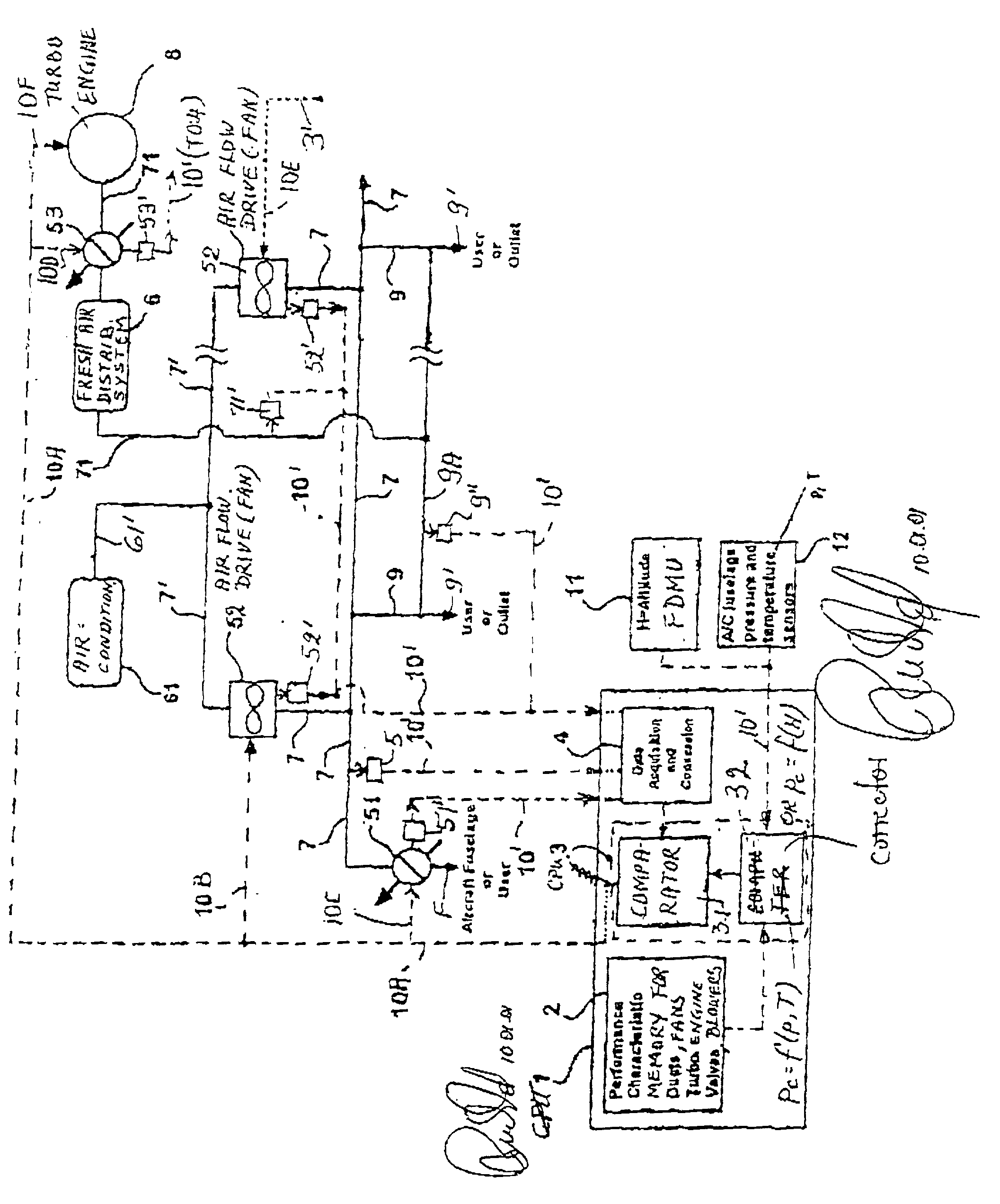
[0026] The single FIGURE shows a closed loop control unit 1 which is preferably part of a central processing unit (CPU). The control unit 1 includes a memory 2 for storing rated or standardized performance characteristic values or data relating to at least certain elements or components of an air mass flow distribution system including pipes 9, ducts 7, 7', 61', 71, valves 51, 53 fans or blowers 52, a climate pack or air conditioner 61, a fresh air distribution system 6, and at least one turbo-engine 8 for providing fresh air. The network will be described in more detail below. The control unit 1 or CPU further comprises a control output 3 of a comparing circuit 31 and a computer 32. The computer 32 has stored in its memory (not shown) an algorithm for calculating updated performance characteristic values based on data representing standardized, rated performance characteristic curves or fields of such curves stored in a memory 2 of the CPU and on data received from sensors 11 and 1...


PUM


Abstract

An air mass or volume flow in an aircraft is controlled in a closed loop control system. A controllable air distribution network is formed by pipes, ducts, valves, fans, a fresh air supply and climate packs. The generation of a closed loop control signal is based on a continuous recalculation or updating of rated performance characteristic data with regard to current pressure, temperature and altitude data. The updated data are compared with actually measured current data to produce the control signal. The rated performance characteristic data are stored in a memory connected to a connected (32) which also receives the current data. The sensing ascertains one or more temperature, pressure, altitude and flow volume data to provide current actually measured data which are then compared with the updated data for generating the closed loop control signal for at least certain of the valves, fans, and fresh air supply.

Description

[0001] This application is based on and claims the priority under 35 U.S.C. .sctn.119 of German Patent Application 100 00 669.8, filed on Jan. 11, 2000, the entire disclosure of which is incorporated herein by reference.[0002] An air mass or air volume flow, particularly in a distribution network in a passenger aircraft cabin is controlled by controlling the flow through the distribution network in response to a plurality of parameters such as the flight altitude, which parameters have an influence on the flow volume.BACKGROUND INFORMATION[0003] In aircraft and particularly in passenger aircraft it is important for the passengers' comfort that an air mass flow through the cabin is balanced. This means that the air volume supplied into the cabin must be balanced relative to the air volume taken out of the cabin at any altitude, at any temperature and at any cabin pressure. Pressures and temperatures inside and outside of the aircraft are parameters that have an influence on the air m...

Claims


Application Information

Patent Timeline
IPC IPC(8): B64D13/00
CPCB64D13/00
Inventor BUCHHOLZ, UWE ALBERT
Owner AIRBUS OPERATIONS GMBH
Why Eureka
Eureka Blog
Learn More