CDMA encoder-decoder, CDMA communication system, WDM-CDMA communication system

a communication system and encoder technology, applied in multiplex communication, optical code multiplex, instruments, etc., can solve the problems of deteriorating the s/n ratio (signal to noise ratio) at the receiver, increasing the loss, and unnecessary optical pulses being produced to deteriorate the s/n ratio of the signal

Inactive Publication Date: 2001-08-02
NIPPON TELEGRAPH & TELEPHONE CORP
View PDF0 Cites 28 Cited by
  • Summary
  • Abstract
  • Description
  • Claims
  • Application Information

AI Technical Summary

Problems solved by technology

However, when the settings do not satisfy the decoding conditions, an inputted encoded pulse is further spread in the time region and is not decoded.
The conventional method described above, however, has a problem that side lobe components are produced around the decoded optical pulse, and the S/N ratio (Signal to Noise ratio) at the receiver is deteriorated even when the decoding condition is satisfie...

Method used


Image

  • CDMA encoder-decoder, CDMA communication system, WDM-CDMA communication system
  • CDMA encoder-decoder, CDMA communication system, WDM-CDMA communication system
  • CDMA encoder-decoder, CDMA communication system, WDM-CDMA communication system

Examples


second embodiment

[0125] Since the light passes the delay lines 48a-48h twice, these delay lines are arranged so that the length difference from the neighbor differs by Lm / 2. The operation as an optical CDMA encoder-decoder is the same as that described in the

sixth example

[0126] Now a sixth embodiment of the present invention is explained below by referring to FIGS. 12 to 15. Explanation of the same components and numerals as those described above is omitted.

[0127] In this example, the optical CDMA encoder-decoder is constructed by connecting a first arrayed-waveguide grating, variable delay lines, and a second arrayed-waveguide grating in this order.

[0128] Specific examples are described below for detailed explanation.

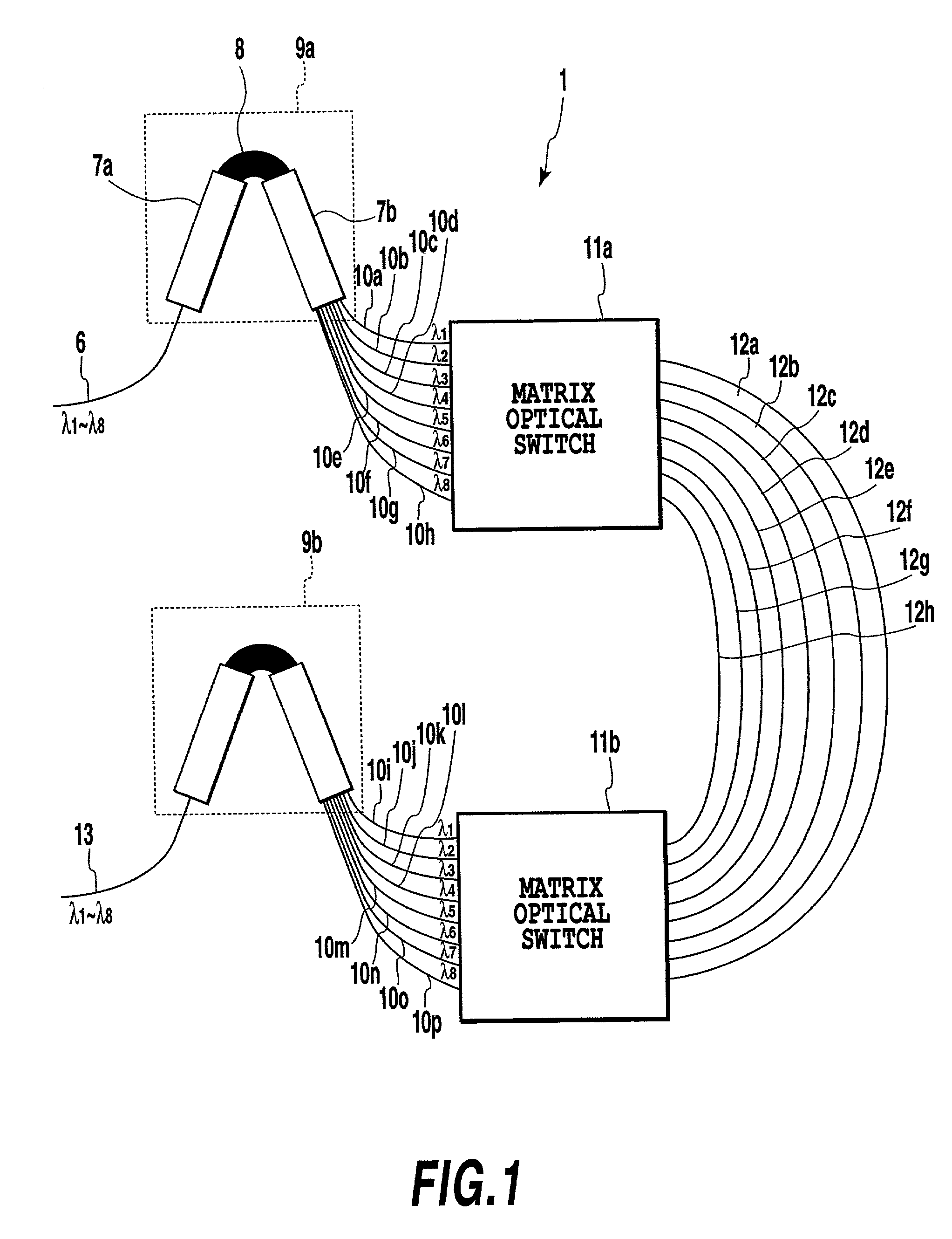
[0129] FIG. 12 shows the configuration example of the optical CDMA encoder-decoder 1. The CDMA encoder and the CDMA decoder are formed on separate substrates using the configuration shown in FIG. 12.

[0130] In FIG. 12, the optical CDMA encoder-decoder 1 comprises an input part 53, arrayed-waveguide gratings 54a, 54b, waveguides 55a-55p, variable delay lines 56a-56h, and an output part 57.

modified example 1

[0131] The other configuration example of the variable delay lines described in FIG. 13 can be used in FIG. 12. Cascaded asymmetrical Mach-Zehnder interferometers in series can be used as the variable delay lines.

[0132] FIG. 13 shows the configuration example of the variable delay lines 56a-56h.

[0133] The variable delay lines 56a-56h are constructed using input waveguides 58a and 58b, 2.times.2 optical switches 59-1 to 59-N+1 (N: natural number), pairs of asymmetrical arms 60a-1 to 60a-N and 60b-1 to 60b-N, and output waveguides 61a and 61b.

[0134] Either 58a or 58b is used as the input, and either 61a or 61b is used as the output. In this case, the optical path length difference .DELTA.L of the pair of asymmetrical arms 60 is set at .DELTA.L.sub.N=2.sup.N-1c.tau..sub.0 / n. Various optical lengths can be set when changing the switching state of the 2.times.2 optical switch 59, and then the variable delay lines can be realized.

[0135] The variable delay lines are arranged so that the op...


PUM


Abstract

An optical CDMA encoder-decoder is constructed by combining arrayed-waveguide gratings, matrix optical switches, and delay lines, otherwise by combining arrayed-waveguide gratings and variable delay lines, thus providing an encoding process that a wavelength change with respect to time in optical pulses.

Description

[0001] This application is based on Patent Application No. 2000-1046 filed on Jan. 6, 2000 in Japan, the content of which is incorporated hereinto by reference.[0002] 1. Field of the Invention[0003] The present invention relates to an encoder-decoder, and a CDMA (Code Division Multiple Access) communication system, especially, relates to a CDMA encoder-decoder and a CDMA communication system in an optical area wherein encoding and decoding of a signal can be carried out.[0004] Also, this invention relates to a WDM (Wavelength Division Multiplexing)-CDMA communication system in an optical area wherein a CDMA technique is applied to a WDM communication.[0005] 2. Description of the Related Art[0006] In an optical CDMA system, it is systematically possible to realize random access and self routing operation by encoding and decoding signals without using a component such as an optical switch. Therefore, this system can be applicable to an optical LAN and an optical switching system.[0007...

Claims


Application Information

Patent Timeline
IPC IPC(8): G02B6/28G02B6/34H04J14/00H04J14/02
CPCG02B6/12021G02B6/2861H04J14/005H04J14/02
Inventor TAKIGUCHI, KOICHIOKAMOTO, KATSUNARISHIBATA, TOMOHIROKATO, MASAOGOH, TAKASHI
Owner NIPPON TELEGRAPH & TELEPHONE CORP
Why Eureka
Try Eureka