Electrostatic recording method and electrostatic recording apparatus

a recording method and electrostatic technology, applied in the direction of electrographic process apparatus, instruments, optics, etc., can solve the problems of disturbance of printing image, difference in relative speed, and difficulty in keeping the running speed of recording medium and electrostatic recording body at the same speed, so as to prevent the generation of transfer blur and print disassembly

Inactive Publication Date: 2001-08-02
KOKI HLDG CO LTD
View PDF0 Cites 11 Cited by
  • Summary
  • Abstract
  • Description
  • Claims
  • Application Information

AI Technical Summary

Benefits of technology

[0033] The object of the present invention is to provide an electrostatic recording method and an electrostatic recording apparatus, by which the Paschen discharge generated in the separation process of the recording medium and the electrostatic recording body can be prevented, and the generation of the transfer blur and the print disarrangement can be prevented.

Problems solved by technology

However, when the contact surface of the recording medium with the electrostatic recording body is increased, it is difficult to keep the running speed of the recording medium and the electrostatic recording body at the same speed, and according to the relative speed difference, another problem in which the disturbance of the printing image is generated due to the difference of the relative speed, is generated.
Further, in the structure in which the recording medium and the electrostatic recording body are brought into contact with each other under the flat condition, the electrostatic recording body is used, for example, as a thin seamless photoreceptor belt, however, the generation of the extension and contraction due to the change of temperature or humidity of the belt material, or elongation or sagging in the use for the long period of time, is the problem to be overcome in the high speed printing.
However, when the electrostatic recording body is the photoreceptor drum, the actual condition is that the pre-separation AC discharging just after the transferring is difficult from the viewpoint of the apparatus structure.
From above description, in the separation process after the transfer, although the electrostatic recording body is the photoreceptor drum or photoreceptor belt, it is a problem of the high resolusion printing to realize the lowering of the voltage of the recording medium and the electrostatic recording body, and no-charging condition of them.

Method used


Image

  • Electrostatic recording method and electrostatic recording apparatus
  • Electrostatic recording method and electrostatic recording apparatus
  • Electrostatic recording method and electrostatic recording apparatus

Examples


Embodiment Construction

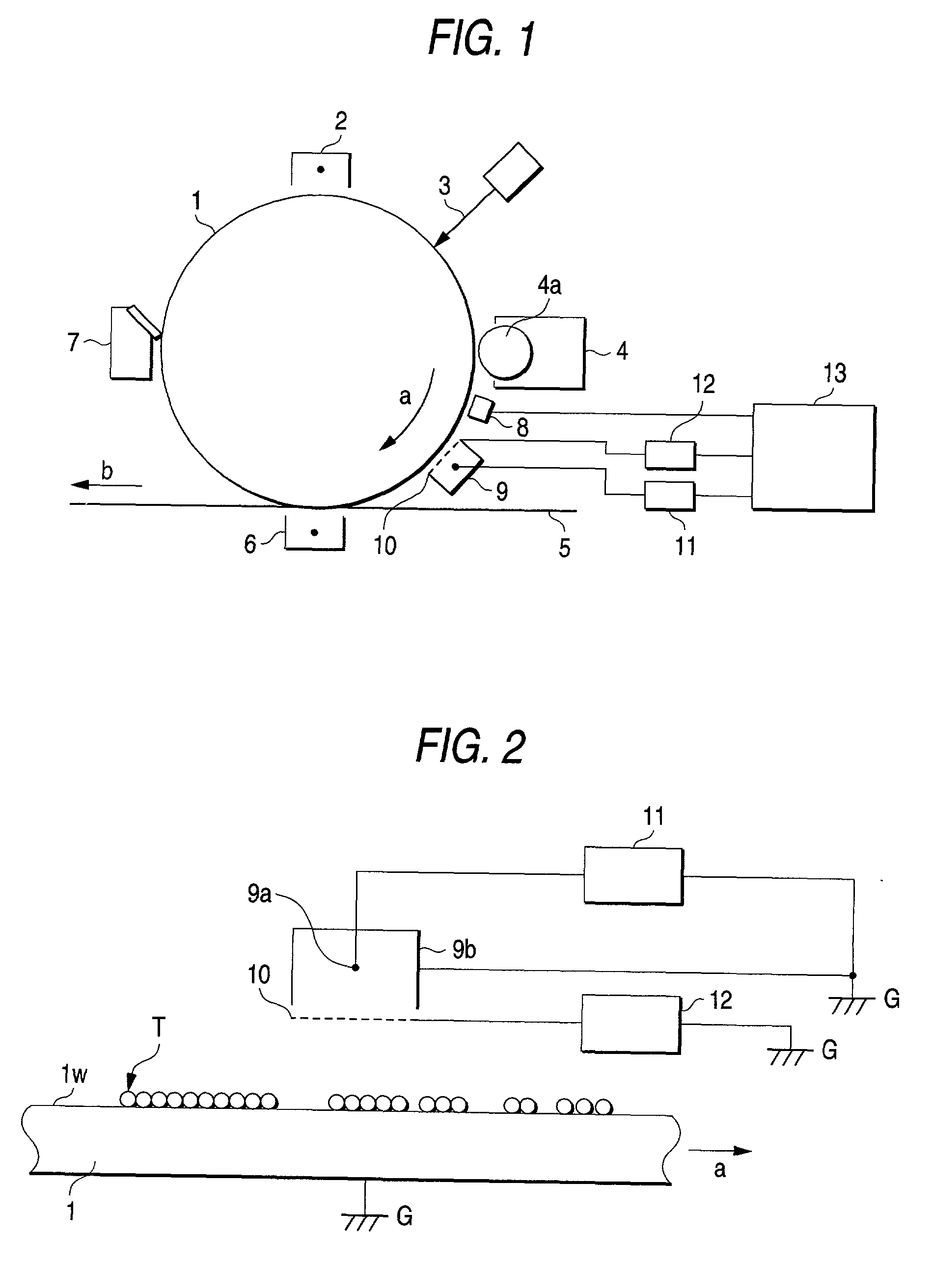
[0057] An embodiment of the present invention will be described below. Initially, referring to FIG. 7 to FIG. 10, an electrostatic recording method according to the first to the sixth aspect of the invention will be detailed.

[0058] In order to make the transfer mechanism clear, 5-layer model shown in FIG. 7 will be adopted herein.

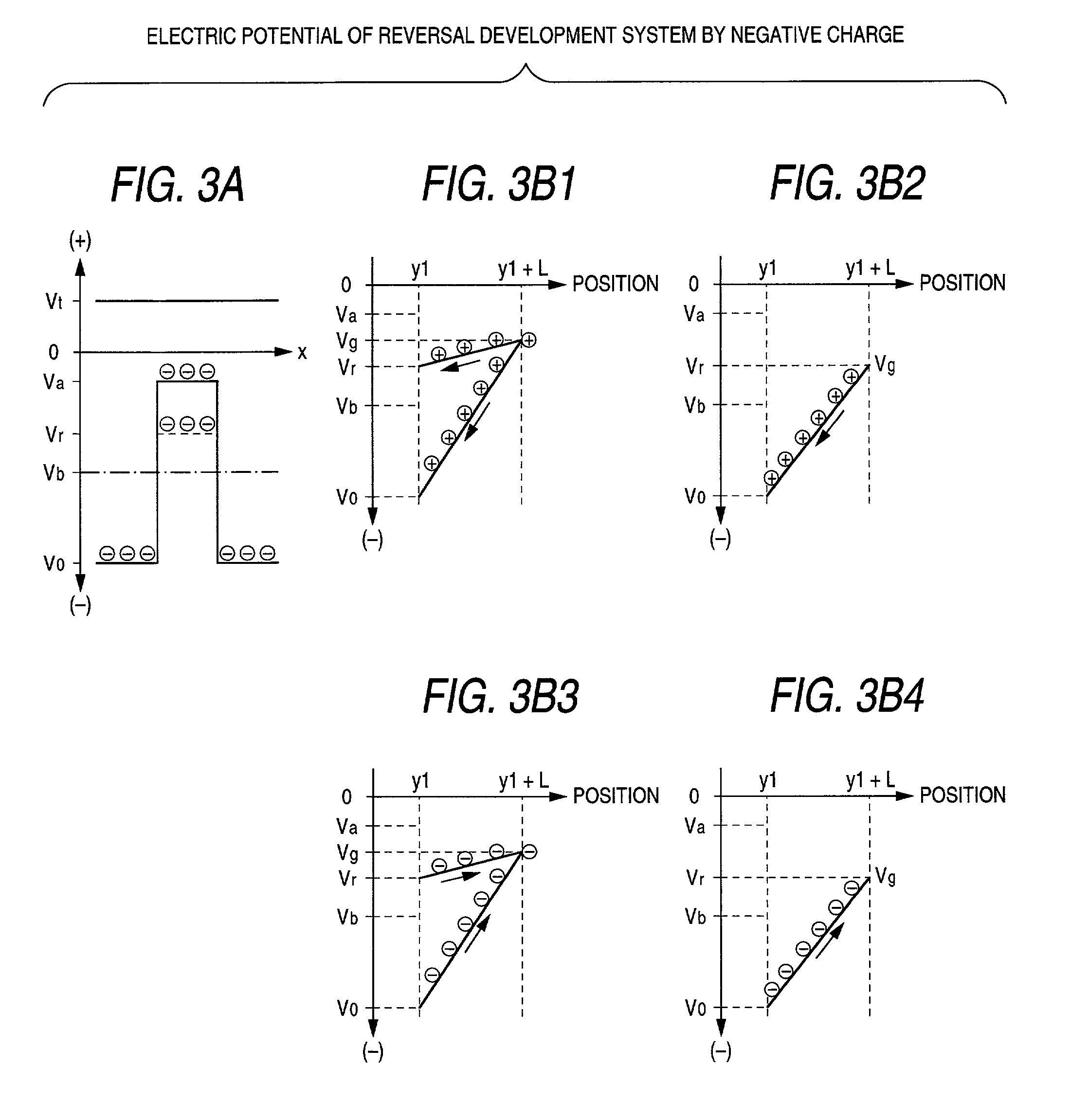
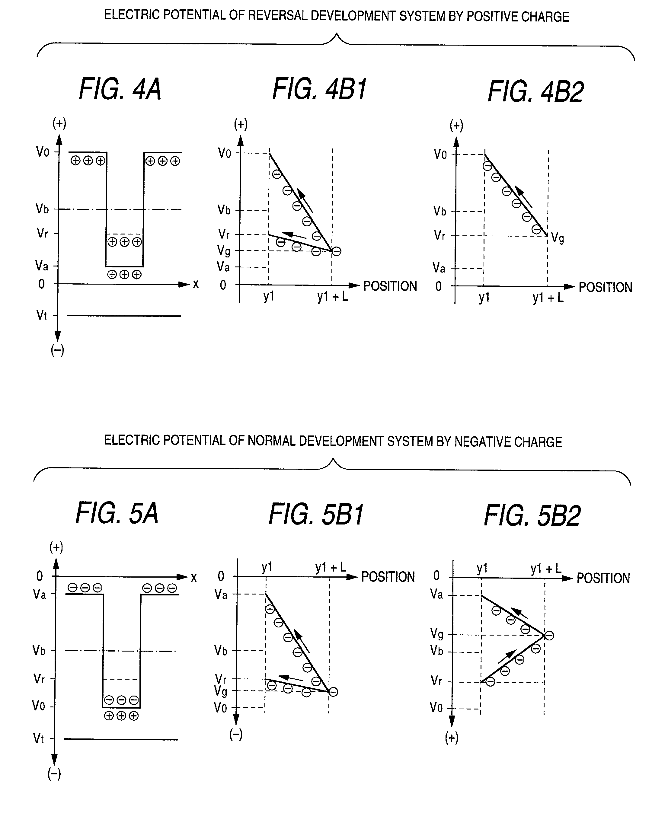
[0059] The first layer (1) is an electrostatic recording body layer whose rear surface is electrically grounded (mainly electrophotographic photoreceptor), and the thickness d.sub.1, dielectric constant .epsilon..sub.1, and dielectric thickness D.sub.1=d.sub.1 / .epsilon..sub.1-. Herein, as the developing method, the reversal developing method is adopted, and as the initial surface potential is V.sub.0, the potential of an area which is developed by the recording agent (toner) is Va, it will be described below. In this case, the relationship of the potential of each area and the surface electric charge density can be given by V.sub.0=.sigma.D.sub.1, Va=.sigma...


PUM


Abstract

Prior to the transfer process, the pre-transfer charging is conducted on the recording image formed on the electrostatic recording body by the development process, and the potential difference generated in the air gap between the recording medium and the recording image at the time of transfer, is made smaller than the Paschen discharge potential difference.

Description

[0001] 1. Field of the Invention[0002] The present invention relates to an electrostatic recording method appropriate for obtaining a highly fine recording image, and to an electrostatic recording apparatus.[0003] 2. Description of the Related Art[0004] A digital printing machine which is known as a form of the electrostatic recording apparatus has an advantage exceeding the conventional printing method, and as being represented by on-demand-publishing, a high speed and high resolusion printing method is investigated.[0005] Also in the electronic photographing method which is representative as the recording method used in the electrostatic recording apparatus, in order to attain these requirements, covering over the optical system, electrostatic recording body (for example, dielectric body, or photoreceptor), development engineering, electrostatic transfer engineering, heating-pressure-fixing engineering, and cleaning system, a series of improvements are advanced.[0006] Then, as the...

Claims


Application Information

Patent Timeline
Patent Type & Authority Applications(United States)
IPC IPC(8): G03G15/16
CPCG03G15/169
Inventor FURUYA, YUJIMATSUMOTO, HIROYOSHI
Owner KOKI HLDG CO LTD
Why Eureka
Try Eureka