Deferral of transmissions in wireless local area network

a wireless local area network and transmission technology, applied in the field of transmission deferral of wireless local area network, can solve the problems of inability to determine the level of signal detected by the first network from transmissions made within the second network, too attenuated or noisy to be decoded by the computing entities comprising the wireless network, and the limited use of physical hard wired infrastructure of commercial local area networks (lans) in widespread applications

Inactive Publication Date: 2001-08-16
HEWLETT PACKARD DEV CO LP
View PDF0 Cites 32 Cited by
  • Summary
  • Abstract
  • Description
  • Claims
  • Application Information

AI Technical Summary

Problems solved by technology

However, until relatively recently, such commercial local area networks (LAN) were limited to a physical hard wired infrastructure in widespread applications.
However, there is a problem encountered with such a collision avoidance protocol if a remote computing entity outside of the network is located with respect to the wireless network such that data packets transmitted by the remote computing entity are required, but are too attenuated or noisy to be decoded by the computing entities comprising the wireless network.
The level of signal detected by the first network from transmissions made within the second network may not be high enough to be able to determine which particular computing entity the transmission is intended for.
However, since the first network entities operate on the principle of deferring their own transmission where there is already a transmission on the frequency, internal communications between entities of the second network interfere with the operation of the first network.
This constitutes inefficient use of frequency bandwidth, and the problem increases where a large number of networks are included in physical proximity in an indoor environment.
Even though the transmissions of the remote computing entity outside the network cannot be decoded by computing entities within the network, their presence inhibits communications between the entities in the network.

Method used


Image

  • Deferral of transmissions in wireless local area network
  • Deferral of transmissions in wireless local area network
  • Deferral of transmissions in wireless local area network

Examples


Embodiment Construction

[0027] There will now be described by way of example the best mode contemplated by the inventors for carrying out the invention. In the following description numerous specific details are set forth in order to provide a thorough understanding of the present invention. It will be apparent however, to one skilled in the art, that the present invention may be practiced without limitation to these specific details. In other instances, well known methods and structures have not, been described in detail so as not to unnecessarily obscure the present invention.

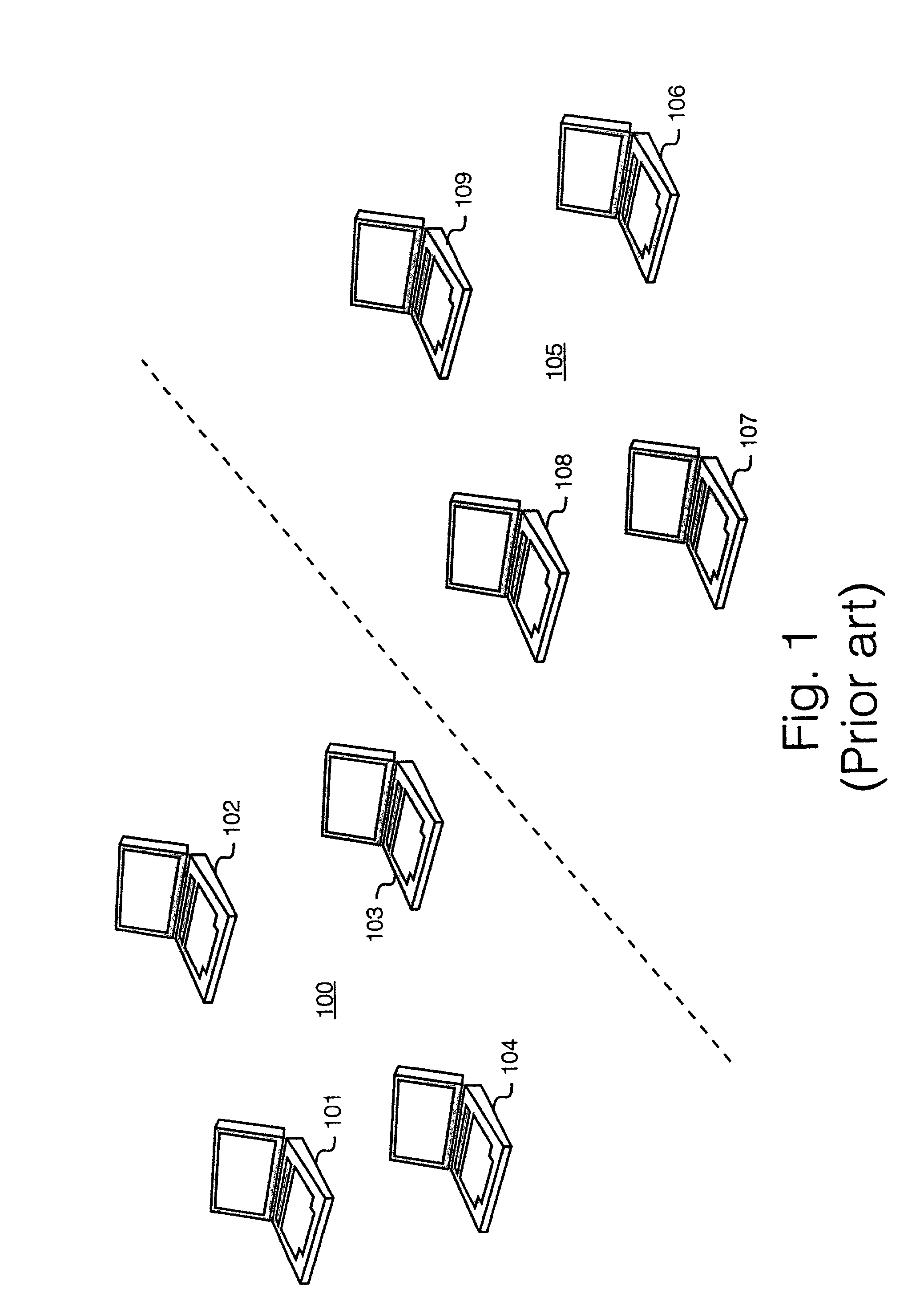
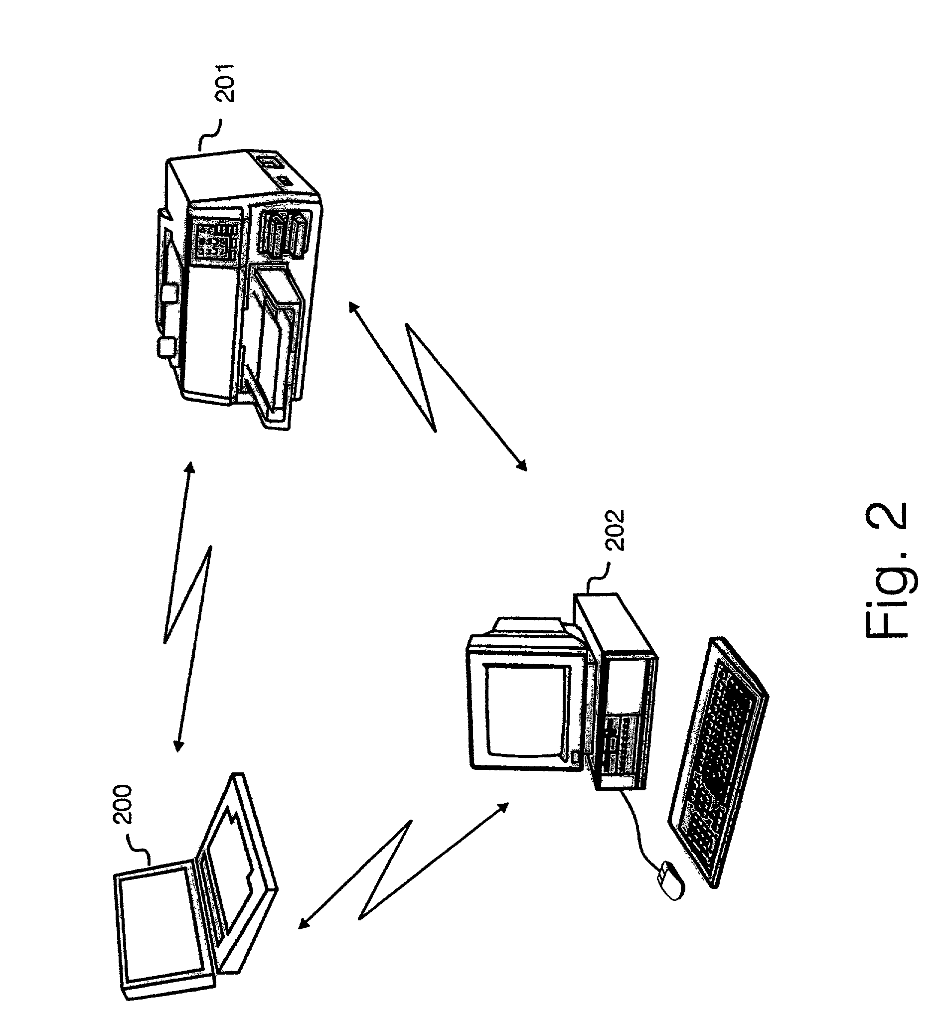
[0028] In this specification, the term "local area network" is used to describe a plurality of computing entities which are interconnected to communicate with each other over a local area. The geographical extent of a local area can range from the order of a few meters to a few tens of meters. In the best mode implementation described herein, wireless links are designed and optimized to operate over distances of around 10 meters bet...


PUM


Abstract

A wireless local area network comprising a plurality of computing entities communicating over a common communications frequency within a local area network operates a transmission deferral method whereby each computing entity defers its own transmissions if it receives a signal at said communications frequency which is above a threshold value set within said computing entity, and which is decodable. Each computing entity is capable of varying dynamically the value of its threshold level above which receipt of signals results in the computing entity deferring its own transmission. Received signals on the communications frequency which are less than the threshold value do not result in the computing entity deferring its transmissions, but are ignored by the computing entity. The threshold value is varied according to whether traffic from more remote signal sources are sufficiently intense that the local traffic cannot be decoded.

Description

[0001] The present invention relates to a method for maximizing channel use in a wireless network comprising a plurality of nodes. The invention is of particular significance where the nodes are computing entities, particularly but not exclusively a plurality of networked computers in an indoor environment.BACKGROUND TO THE INVENTION[0002] Since the early 1970's, the success of the Ethernet project and other similar digital protocols has demonstrated the power and flexibility resulting from a plurality of computers sharing information across a digital network. However, until relatively recently, such commercial local area networks (LAN) were limited to a physical hard wired infrastructure in widespread applications.[0003] In order to address a requirement for increased flexibility in computer networks there has been a drive to develop wireless local area networks whereby a plurality of computing entities such as personal computers, laptop computers, printers and the like exchange da...

Claims


Application Information

Patent Timeline
IPC IPC(8): H04B17/00H04B17/382H04L12/28H04L12/801H04L12/825
CPCH04L47/10H04L47/14H04L47/266H04W12/10H04W24/00H04W48/02H04W84/12H04W28/021H04W28/0236H04W8/04
Inventor JOHNSON, IAN ROBERTSHAO, ZHIMINLAWTON, MICHAEL CASE
Owner HEWLETT PACKARD DEV CO LP
Why Eureka
Try Eureka