Metal-air fuel cell battery systems having a metal-fuel card storage cassette, insertable within a port in a system housing, containing a supply of substantially planar discrete metal-fuel cards, and fuel card transport mechanisms therein

a fuel cell battery and metal-air technology, which is applied in the direction of primary cell maintenance/service, cell components, secondary cell servicing/maintenance, etc., can solve the problems of unfavorable fcb rechargeable systems, large volume of physical space required by prior art fcb systems to accommodate enlarged recharging electrodes, and remain unsolved

Inactive Publication Date: 2001-08-16
REVEO
View PDF0 Cites 13 Cited by
  • Summary
  • Abstract
  • Description
  • Claims
  • Application Information

AI Technical Summary

Benefits of technology

[0012] Accordingly, a primary object of the present invention is to provide an improved method and apparatus of discharging and recharging metal-air fuel cell batteries (FCB) in a manner which avoids the shortcomings and drawbacks of prior art technologies.

Problems solved by technology

In practice, however, a number of important problems have remained unsolved which has hitherto rendered rechargeable FCB systems commerically unfeasible.
In particular, prior art FCB systems have required very large volumes of physical space to accomodate enlarged recharging electrodes.
In practice, this is often not possible, or practical.
Prior art FCB systems have sufferered from problems associated with over and under recharging oxidized metal-fuel tape and sheets produced during discharging operations.
Consequently, it has not been possible to optimally recharge metal-fuel tape and sheets using prior art tape recharging systems and methodologies.
Also, using prior art FCB systems it has not been possible to optimally discharge metal-fuel tape and sheets using prior art tape recharging systems and methodologies.

Method used


Image

  • Metal-air fuel cell battery systems having a metal-fuel card storage cassette, insertable within a port in a system housing, containing a supply of substantially planar discrete metal-fuel cards, and fuel card transport mechanisms therein
  • Metal-air fuel cell battery systems having a metal-fuel card storage cassette, insertable within a port in a system housing, containing a supply of substantially planar discrete metal-fuel cards, and fuel card transport mechanisms therein
  • Metal-air fuel cell battery systems having a metal-fuel card storage cassette, insertable within a port in a system housing, containing a supply of substantially planar discrete metal-fuel cards, and fuel card transport mechanisms therein

Examples


Embodiment Construction

Of the Present Invention should be read in conjunction with the accompanying Drawings, wherein:

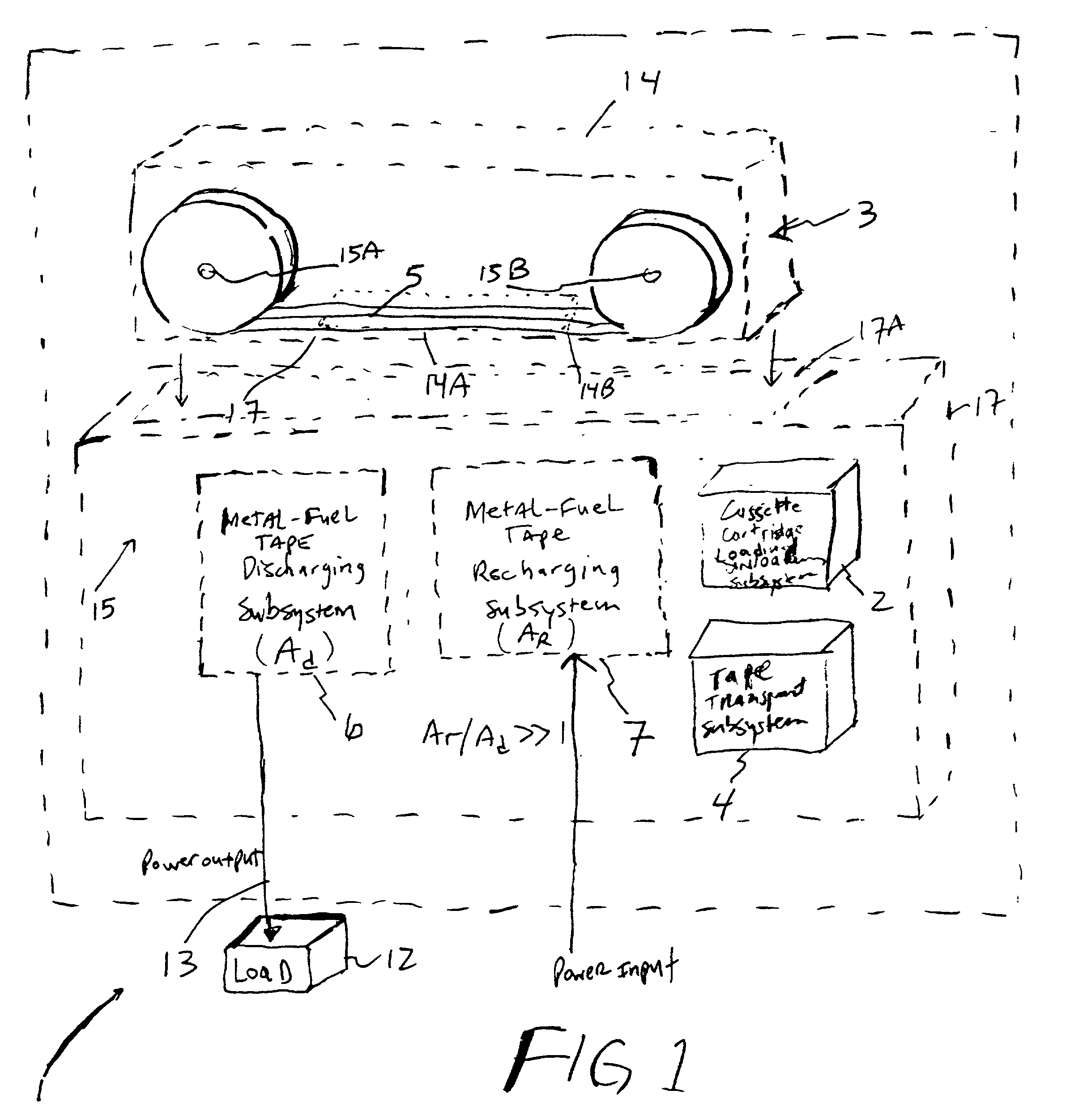
[0055] FIG. 1 is a schematic block diagram of a first illustrative embodiment of the metal-air FCB system of the present invention, wherein a Metal-Fuel Tape Discharging Subsystem and a Metal-Fuel Tape Recharging Subsystem are integrated within a single, stand-alone rechargeable power generation unit, and the tape path-length extension mechanism employed in the Metal-Fuel Tape Recharging Subsystem extends oxidized metal-fuel tape over a path-length which is substantially greater than the path-length maintained by the tape path-length extension mechanism in the Metal-Fuel Tape Discharging Subsystem (i.e. A.sub.Recharge>>A.sub.Discharge);

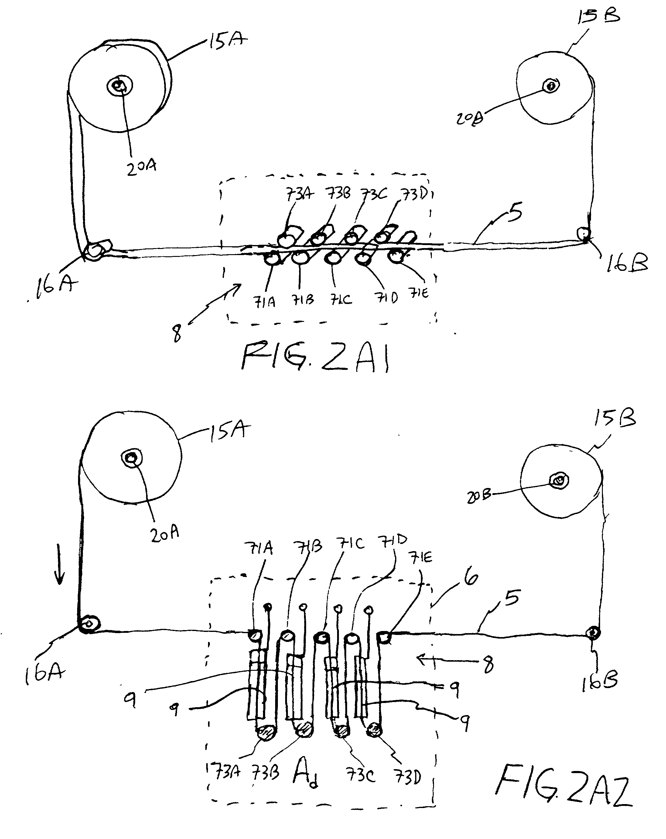
[0056] FIG. 2A1 is a generalized schematic representation of the Metal-Fuel Tape Discharging Subsystem of FIG. 1, wherein the tape path-length extension mechanism associated therewith is shown in its non-extended configuration;

[0057] FIG. 2A2 is a generalize...


PUM

PropertyMeasurementUnit
electrical poweraaaaaaaaaa
structureaaaaaaaaaa
path-lengthaaaaaaaaaa

Abstract

Disclosed are various types of metal-air FCB-based systems comprising a Metal-Fuel Transport Subsystem, a Metal-Fuel Discharging Subsystem, and a Metal-Fuel Recharging Subsystem. The function of the Metal-Fuel Transport Subsystem is to transport metal-fuel material, in the form of tape, cards, sheets, cylinders and the like, to the Metal-Fuel Discharge Subsystem, or the Metal-Fuel Recharge Subsystem, depending on the mode of the system selected. When transported to or through the Metal-Fuel Discharge Subsystem, the metal-fuel is discharged by (i.e. electro-chemically reaction with) one or more discharging heads in order produce electrical power across an electrical load connected to the subsystem while H2O and O2 are consumed at the cathode-electrolyte interface during the electro-chemical reaction. When transported to or through the Metal-Fuel Recharging Subsystem, discharged metal-fuel is recharged by one or more recharging heads in order to convert the oxidized metal-fuel material into its source metal material suitable for reuse in power discharging operations, while O2 is released at the cathode-electrolyte interface during the electro-chemical reaction. In the illustrative embodiments, various forms of metal fuel can be discharged and recharged in an efficient manner to satisfy a broad range of electrical loading conditions.

Description

RELATED CASES[0001] This is a Continuation-in-Part of: copending application Ser. No. 08 / 944,507 entitled "High-Power Density Metal-Air Fuel Cell Battery System" by Sadeg Faris, et al. filed Oct. 6, 1997, said application being assigned to Reveo, Inc. and incorporated herein by reference in its entirely.[0002] 1. Field of the Invention[0003] The present invention relates to improved methods and systems for optimally discharging metal-air fuel cell battery (FCB) systems and devices, as well as improved methods and systems for optimally recharging the same in a quick and efficient manner.[0004] 2. Description of the Prior Art[0005] In copending U.S. application Ser. No. 08 / 944,507, Applicant discloses several types of novel metal-air fuel cell battery (FCB) systems. During power generation, metal-fuel tape is transported over a stationary cathode structure in the presence of an ionically-conducting medium, such as an electrolyte-impregnated gel. In accordance with well known principle...

Claims


Application Information

Patent Timeline
Patent Type & Authority Applications(United States)
IPC IPC(8): H01M2/02H01M2/12H01M2/16H01M2/36H01M2/38H01M4/00H01M4/02H01M4/42H01M4/70H01M4/86H01M6/50H01M8/04H01M8/10H01M8/18H01M8/22H01M10/42H01M10/44H01M10/46H01M10/48H01M12/06H01M12/08H02J7/00
CPCH01M2/1673H01M4/42H01M4/8605H01M6/5011H01M8/184H01M8/186H01M8/22H01M10/4214H01M10/44H01M12/06H01M12/08H01M2004/024H01M2300/0085H02J7/00Y02E60/522Y02E60/528Y02E60/10Y02E60/50H01M50/46
Inventor FARIS, SADEG M.TSAI, TSEPIN
Owner REVEO
Why Eureka
Try Eureka