
All solid-state omni directional luminary and flashlight

a technology of omni-directional luminaires and flashlights, applied in the field of flashlights, can solve the problems of shortening the life of batons from use in hostile and rugged environments, not waterproof or appear to be submerged in water,

Inactive Publication Date: 2001-08-23
GRACE INDS
View PDF0 Cites 32 Cited by
  • Summary
  • Abstract
  • Description
  • Claims
  • Application Information

AI Technical Summary

Benefits of technology

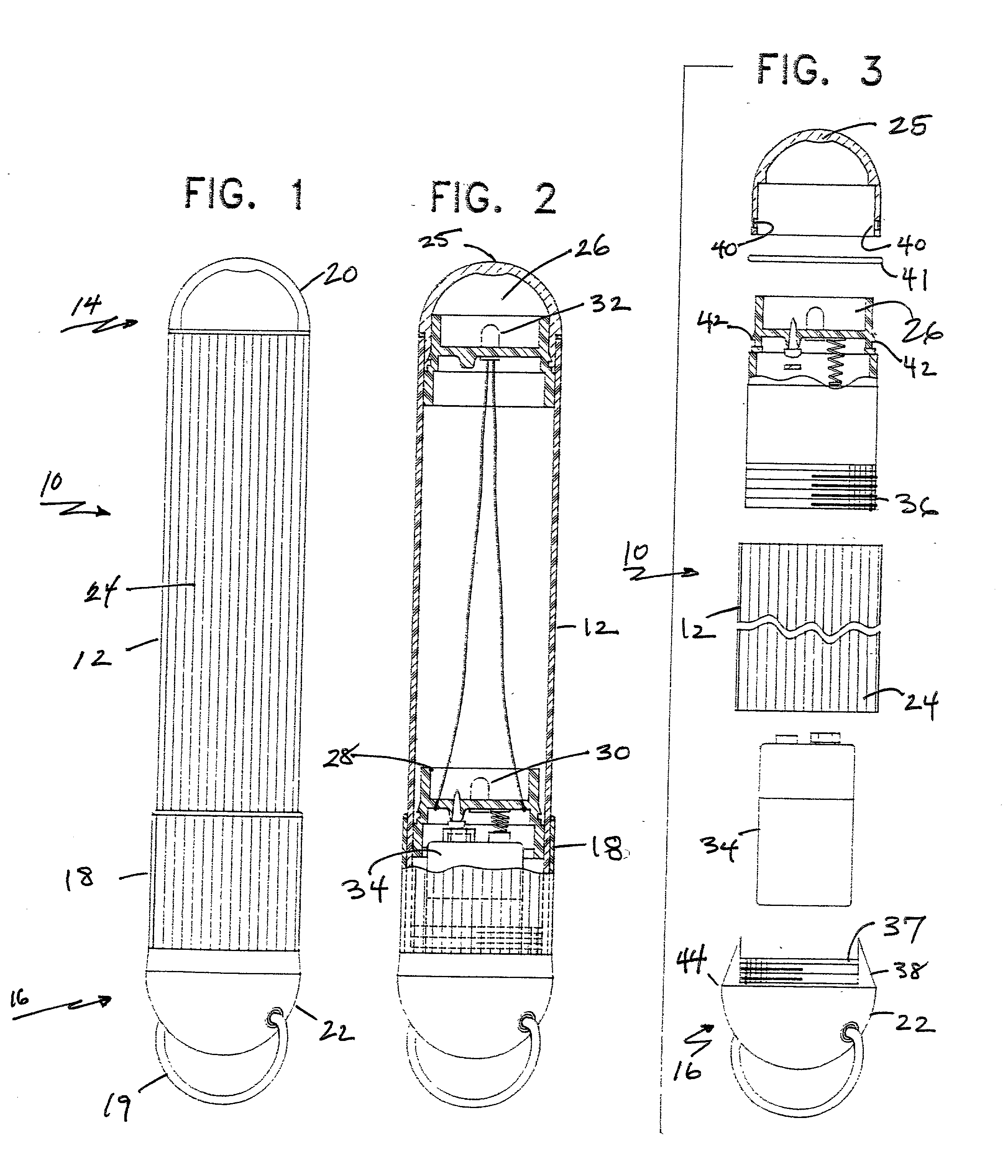
[0016] The mechanical design of the baton is a tube sealed at both ends with hemispheric shaped end caps. This type of design provides an extreme robustness and the baton can withstand extreme depths of submergence, making it useful for deep diving and submergence signaling applications. All interior electronics and solid state light sources are sealed from the outside atmosphere, thus making the glow baton explosion proof and waterproof.
[0017] The hand held light wand of the present invention is a visual signaling light emitting wand. This device is sealed at each end with hemispheric end caps. This shape permits the light wand to withstand extreme depths of submergence, thus making it useful for deep diving signaling applications.
[0021] Another object of the invention is to provide an arrangement of LEDS which cause the tubular polypropylene main body to glow as a luminary and the laser lens assembly projects a beam of light.
[0023] Another object of the invention is to provide machined exterior walls for the light baton to effectively transmit light from the light source.
[0024] A further advantage of the invention is that this type of design is extremely robust and can withstand extreme depths of submergence, making it useful for deep diving and submergence signaling applications.
[0025] It is a further object of the invention to seal all interior electronics and solid state light sources from the outside atmosphere, thus making the glow baton explosion and waterproof.

Problems solved by technology

A common problem encountered in use of light batons is the shortened life span of the baton from usage in hostile and rugged environments.
It is not waterproof or appear to be submersible in water.

Method used


Image

  • All solid-state omni directional luminary and flashlight
  • All solid-state omni directional luminary and flashlight

Examples


Embodiment Construction

[0036] Although only a few preferred embodiments of the invention are explained in detail, and it is to be understood that the embodiments are given by way of illustration only. It is not intended that the invention is to be limited in its scope to the details of construction and arrangement of components set forth in the following description or illustrated in the drawings. The invention is capable of other embodiments and of being practiced or carried out in various ways. Also, in describing the preferred embodiments, specific terminology will be resorted to for the sake of clarity. It is to be understood that each specific term includes all technical equivalents which operate in a similar manner to accomplish a similar purpose.

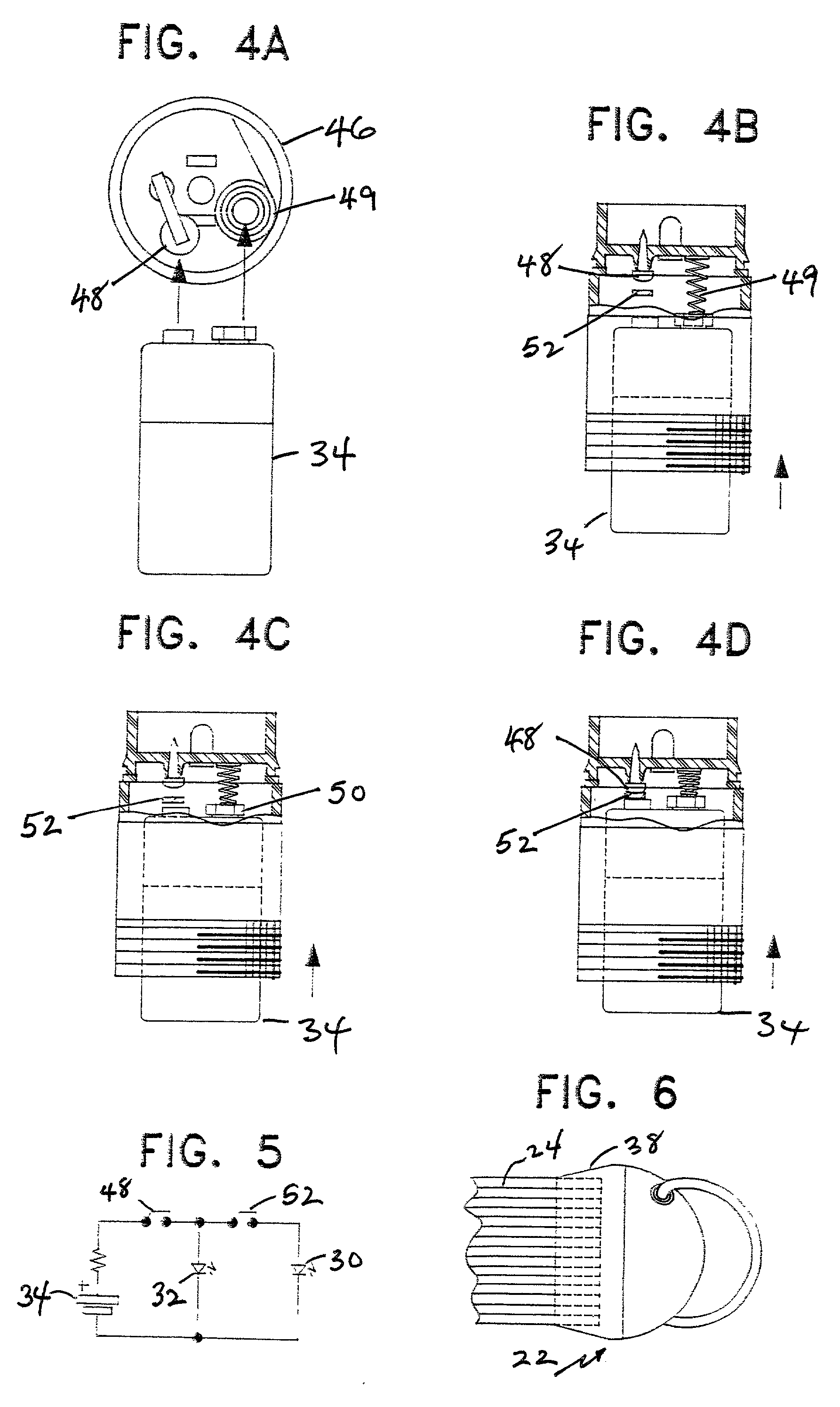
[0037] FIG. 1 depicts a perspective view of an embodiment of the present invention. As shown, the present invention comprises a light baton 10 having an elongated, hollow, tubular body 12. Body 12 includes a contiguous forward portion 14 and rear portion 16...


PUM

PropertyMeasurementUnit
diameteraaaaaaaaaa
diameteraaaaaaaaaa
lengthaaaaaaaaaa

Abstract

A laser lens glow baton is a hand held, dual purpose, visual signaling baton. This device can be used as a flashlight that projects a well-defined beam of light via its laser lens and assembly or as a highly visible luminary that radiates an intense flux of light similar to neon tube. The laser lens glow baton is useful as a visual-signaling device because the colors of the main body and the colors of the projected beam emitted from the laser lens assembly are easily changed. The laser lens glow baton may be easily fabricated in different lengths because of its compartmentalization of the components.

Description

CROSS-REFERENCE TO RELATED APPLICATIONS AND PATENTS[0001] This is a continuation-in-part of patent application Ser. No. 09 / 197,569, filed Nov. 23, 1998.[0002] 1. Field of the Invention[0003] The invention relates to flashlights. More specifically, the present invention is an all solid-state omni directional luminary and flashlight.[0004] 2. The Prior Art[0005] Visual signaling is a common and easily understood method of relaying information from at least one person to another. Visual signaling is often used in environments hostile to other forms of communication. Such environments include traffic intersections, airports, mountain rages, underwater and the like. Provided the environment is hospitable to the transmission of light from a source point to a receiver point, visual signaling provides an effective means of communication.[0006] One type of visual signaling device is a light baton or wand. Light batons are hand held devices which, at the control of the holder, emit colored or...

Claims


Application Information

Patent Timeline
Patent Type & Authority Applications(United States)
IPC IPC(8): F21L4/02F21V5/02F21V9/40F21V15/01F21V25/12F21V31/00F21V33/00G08B5/00G09F13/04
CPCF21L4/02F21V5/02F21V9/10F21V15/01F21V25/12F21V31/00F21V33/0056F21W2111/00F21Y2101/02G08B5/004G09F13/04F21Y2115/10F21Y2113/13F21Y2115/30F21V9/30F21V3/08F21V3/062F21V9/08
Inventor CAMPMAN, JAMES P.
Owner GRACE INDS
Learn More