
Magnetoresistive sensor, a thin film magnetic head, a magnetic head device, and a magnetic disk drive device

a magnetic head and sensor technology, applied in the direction of maintaining head carrier alignment, nanoinformatics, instruments, etc., can solve the problem of inability to realize large mr converting ratio

Inactive Publication Date: 2001-09-27
TDK CORPARATION
View PDF0 Cites 9 Cited by
  • Summary
  • Abstract
  • Description
  • Claims
  • Application Information

AI Technical Summary

Problems solved by technology

However, when the underfilm is made of the above Ta film, Nb film, Zr film, Hf film or the like, a large MR converting ratio can not be realized in spite of the above appropriate material selection for the first ferromagnetic film.

Method used


Image

  • Magnetoresistive sensor, a thin film magnetic head, a magnetic head device, and a magnetic disk drive device
  • Magnetoresistive sensor, a thin film magnetic head, a magnetic head device, and a magnetic disk drive device
  • Magnetoresistive sensor, a thin film magnetic head, a magnetic head device, and a magnetic disk drive device

Examples


Embodiment Construction

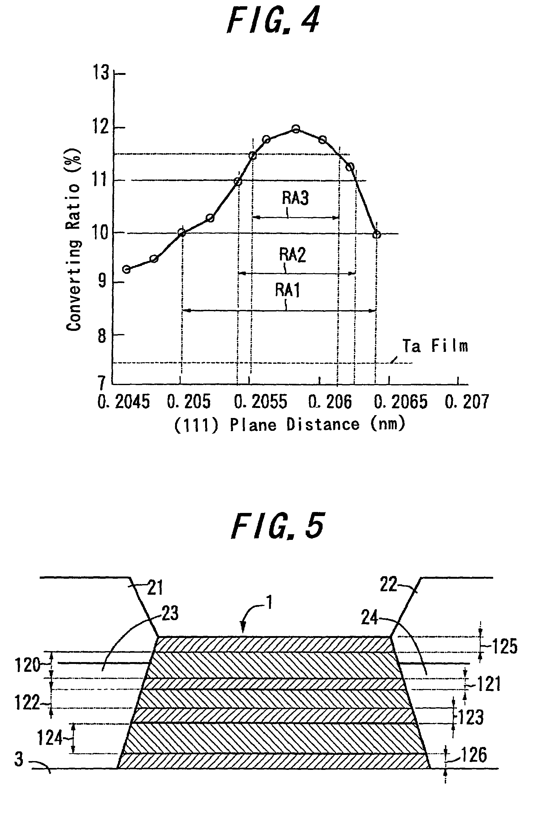
Ta 7.5 Example 1 Ni(60)Cr(40) 12.0 Example 2 Ni(60)Cu(40) 11.8 Example 3 Ni(60)Cr(30)Cu(10) 11.9 Example 4 Ni(60)Fe(5)Cr(35) 12.0 Example 5 Ni(60)Cu(30)Ir(10) 11.1 Example 6 Ni(60)Cu(35)Al(5) 11.2 Example 7 Ni(60)Cu(35)V(5) 11.7 Example 8 Ni(60)Cr(30)Mo(10) 11.6 Example 9 Ni(60)Fe(5)Cr(25)Mn(10) 11.3 Example 10 Co(55)Fe(5)Cr(40) 12.0 Example 11 Co(55)Fe(5)Cu(40) 11.8 Example 12 Co(55)Fe(5)Cu(30)Al(10) 11.3 Example 13 Ni(50)Co(5)Fe(5)Cr(40) 11.5 Example 14 Cu(70)Cr(30) 12.3 Example 15 Cu(70)Cr(20)V(10) 12.2 Example 16 Cu(60)Cr(20)Mo(10)Mn(10) 11.5 Example 17 Cu(75)V(10)Al(15) 11.8

[0062] As is apparent from Table 1, the magnetoresistive sensors shown in Examples 1-17 have large MR converting ratio of 11% or over. The magnetoresistive sensor shown in Example 5 has a minimum MR converting ratio of 11.1%, and the one shown in Example 14 has a maximum MR converting ratio of 12.3%. The magnetoresistive sensor shown in Comparative Example 1 has a MR converting ratio of only 7.5%, so that it...


PUM


Abstract

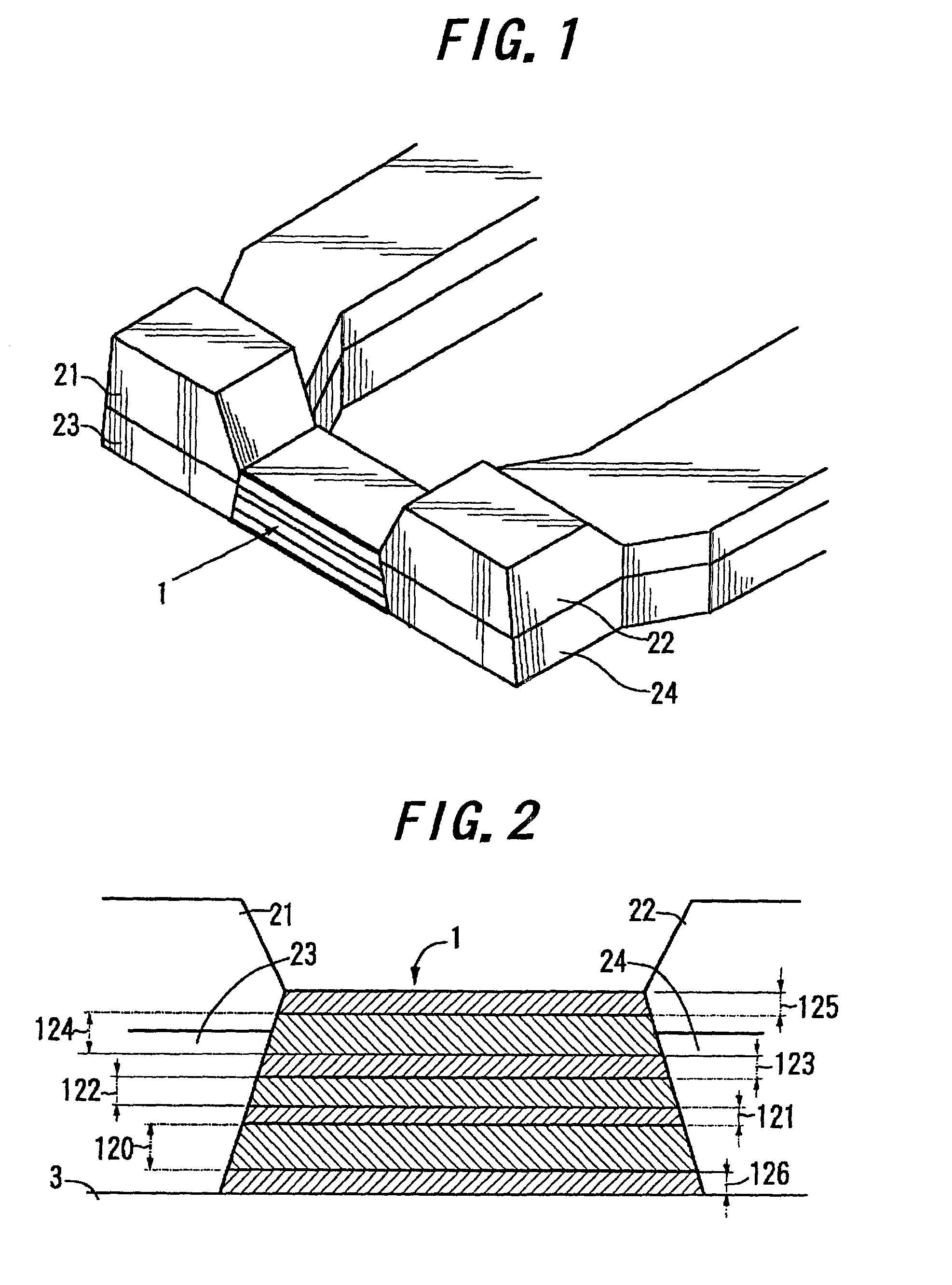
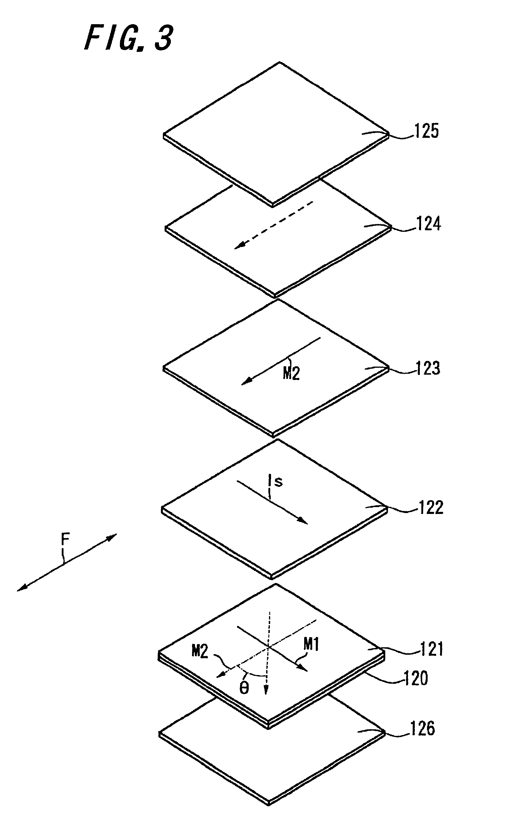
A magnetoresistive sensor according to the present invention has a spin-valve film structure which includes an underfilm, a first ferromagnetic film, a conductive film, a second ferromagnetic film, an antiferromagnetic film and a protective film. One surface of the first ferromagnetic film is adjacent to the one surface of the underfilm, and the one surface of the conductive film is adjacent to the other surface of the first ferromagnetic film. One surface of the second ferromagnetic film is adjacent to the other surface Of the conductive film. One surface of the antiferromagnetic film adjacent to the other surface of the second ferromagnetic film, and thus, the antiferromagnetic film is bonded to the second ferromagnetic film with exchange interaction. One surface of the protective film is adjacent to the other surface of the antiferromagnetic film. The underfilm has a face centered cubic crystal structure, and is oriented in the (111) plane direction. Then, the distance between the adjacent (111) planes of the spin-valve film structure except the antiferromagnetic film is within 0.2050-0.2064 nm.

Description

[0001] 1) Field of the Invention[0002] This invention relates to a magnetoresistive sensor, a thin film magnetic head, a magnetic head device, and a magnetic disk drive device.[0003] 2) Related Art Statement[0004] With recent downsizing of a magnetic disk drive device, a thin film magnetic head having a magnetoresistive sensor which takes advantage of its magnetoresistive effect, has been employed as a magnetic converter suitable for reading data recorded in a magnetic recording medium in a high recording density because its output is not influenced by the relative velocity for the magnetic recording medium.[0005] Conventionally, a reading element with an anisotropic magnetoresistive effective film (hereinafter, called as an "AMR film") made of permalloy or the like is employed as the above magnetic converter, but recently, a reading element with a giant magnetoresistive effective film (hereinafter, called as a "GMR film"), particularly a spin-valve film structure is mainly used. A ...

Claims


Application Information

Patent Timeline
IPC IPC(8): G01R33/09G11B5/00G11B5/127G11B5/39G11B5/48G11B5/596
CPCB82Y10/00B82Y25/00G01R33/093G11B5/1278G11B5/3903G11B5/3967G11B5/4806G11B5/59683G11B2005/0029G11B2005/3996Y10T428/11Y10T428/1193
Inventor TERUNUMA, KOICHISASAKI, TETSUROTANAKA, KOSUKEUESUGI, TAKUMI
Owner TDK CORPARATION
Learn More