Machining centers

a technology of machining centers and machining supports, which is applied in the direction of metal-working holders, supporters, positioning apparatuses, etc., can solve the problems of complex structure and operation of conventional machining centers

Inactive Publication Date: 2001-10-04
MACHINING CENTS MFG
View PDF0 Cites 8 Cited by
  • Summary
  • Abstract
  • Description
  • Claims
  • Application Information

AI Technical Summary

Benefits of technology

0003] An object of the present invention is to obviate the above disadvantage of conventional machining centers by providing a machining center having a configuration which does not require a manipulator arm to perform the loading and unloading operations of the workpiece into and from the machinin...

Problems solved by technology

This configuration of the conventional machining centers is ...

Method used


Image

  • Machining centers
  • Machining centers
  • Machining centers

Examples


Embodiment Construction

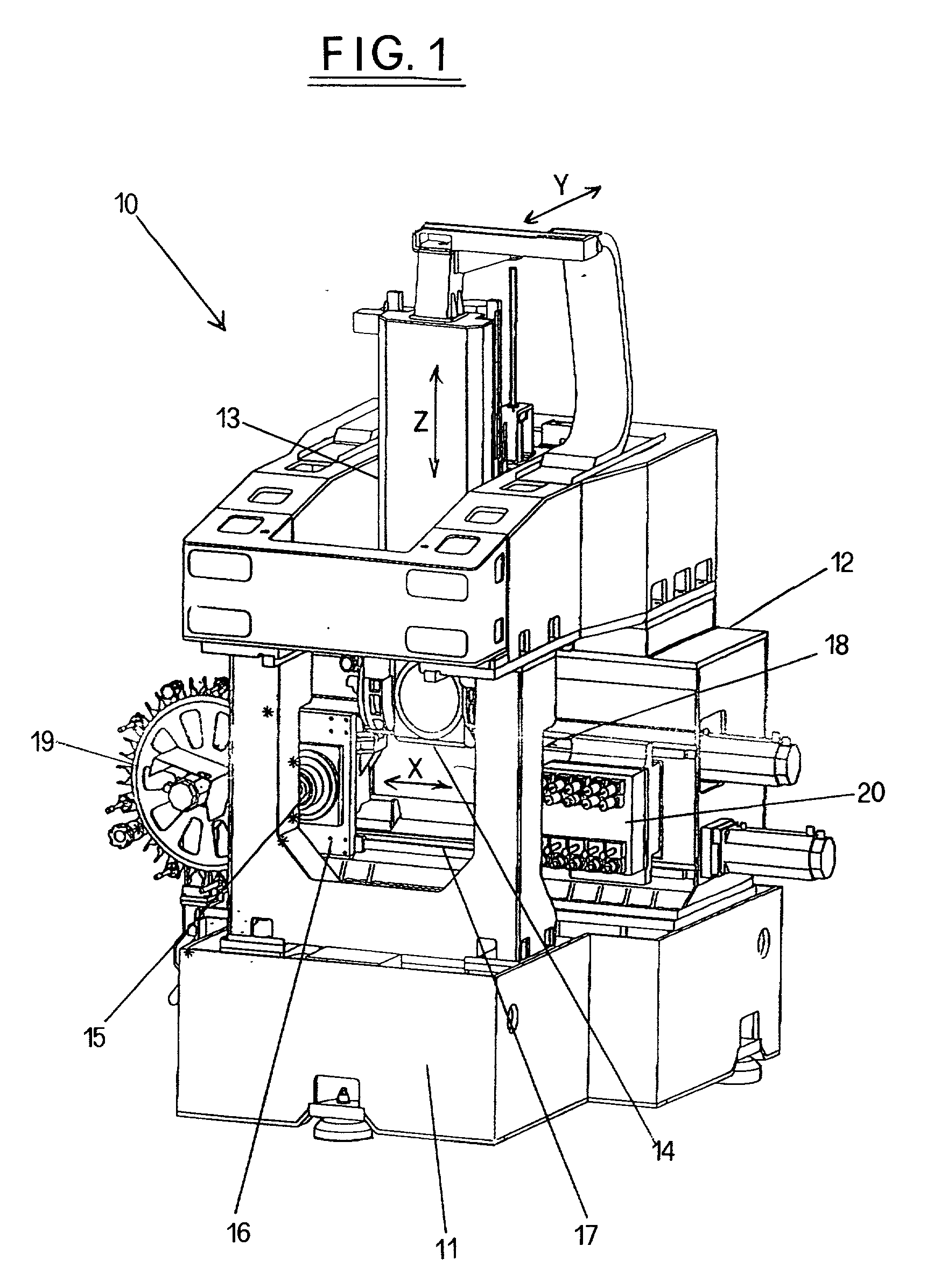
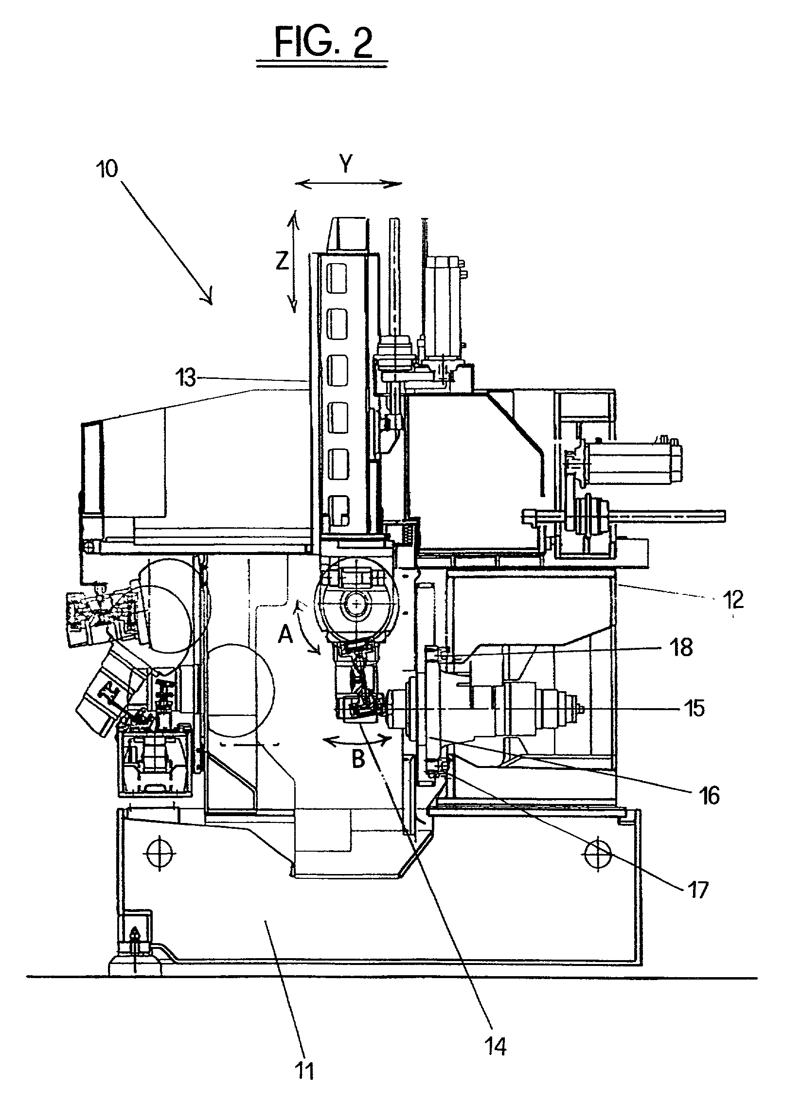
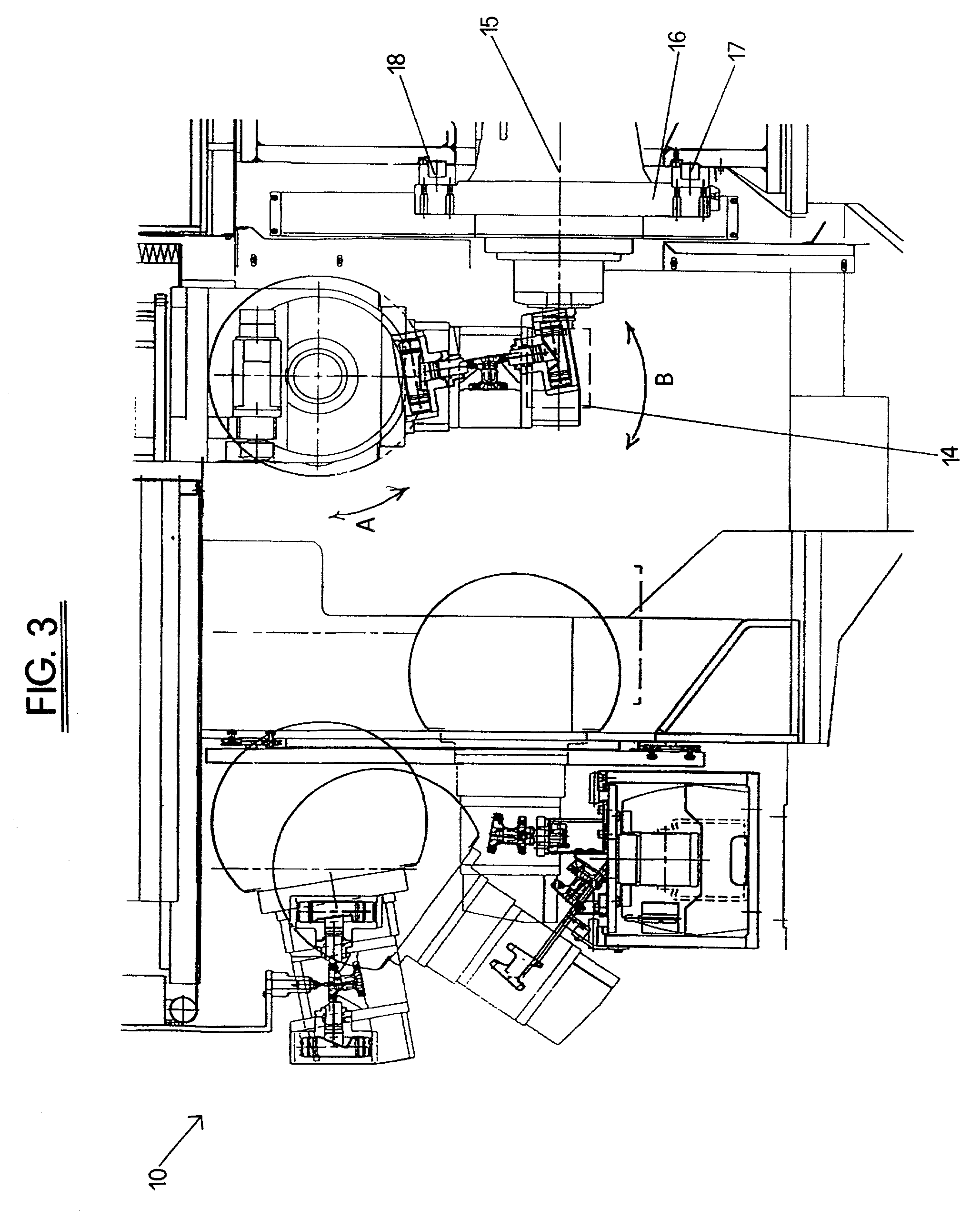
[0009] Referring to the Figures of the drawings there is shown the machining center according to the present invention, generally designated by 10. The machining center 10 comprises a base 11, a frame 12 and a movable vertical member 13 at the lower end of which a workpiece gripping and supporting member 14 is connected.

[0010] The workpiece gripping and supporting member 14 is connected to the lower end of the movable vertical member 13 which is movable along an horizontal axis Y and a vertical axis Z. Furthermore, the workpiece gripping and supporting member 14 is provided with two rotation axes designated by A and B.

[0011] The machining center 10 also includes a machine tool 15 with an horizontal spindle mounted onto a slide 16 which is movable on guides 17,18 along an horizontal axis X. The machining center 10 is also provided with at least a pair of tool magazines 19,20, one of which 19 is of a rotary type, and the other 20 is of the rack type. The pair of tool magazines 19,20 a...


PUM

PropertyMeasurementUnit
Forceaaaaaaaaaa
Gravityaaaaaaaaaa

Abstract

The machining center has a base, a frame and at least a machine tool mounted onto the frame, at least a tool magazine associated with the machine tool for changing the tool and a workpiece gripping and supporting member. The machining center comprises a movable vertical member adapted to support from the top the workpiece gripping and supporting member. The movable vertical member is adapted to position the workpiece gripping and supporting member in a first operative position in which the workpiece is automatically loaded onto or unloaded from the workpiece gripping and supporting member of the machining center and in a second operative position in which the workpiece is machined by the machine tool of the machining center. The gripping and supporting member is adapted to hold firmly the workpiece during the machining operation and support it from the top so that the chips formed by the machine tool during the machining operation fall downwards by force of gravity thereby clearing the machining area from the chips.

Description

BACKGROUND OF THE INVENTION[0001] The present invention generally relates to the field of machine tools and particularly a machining center having an improved configuration including a novel device for loading and supporting a workpiece during machining operation.DESCRIPTION OF THE PRIOR ART[0002] It is known that the machining centers are commonly included in machining systems comprising a plurality of machining centers which are coordinated by a central control unit. The workpieces are fed to the single machining centers and transferred from one machining center to another by means of transporting means arranged near the machining centers and formed of movable pallets. In conventional machining systems there is provided a device for loading a workpiece in the machining center which is formed of a manipulator arm connected to the machining center. This configuration of the conventional machining centers is rather complex from both a structural and operative point of view.SUMMARY OF...

Claims


Application Information

Patent Timeline
IPC IPC(8): B23Q11/00
CPCB23Q11/0053Y10T483/1845Y10T409/30532Y10T409/305376Y10T483/16Y10T483/1733
Inventor BOLLEDI, GIUSEPPE
Owner MACHINING CENTS MFG
Why Eureka
Try Eureka