Systems and methods for automated sensing and machining for repairing airfoils of blades

a technology of automatic sensing and machining, applied in the field of airfoil repair, can solve the problems of airfoils of gas turbine engines that are regularly exposed to harsh operating conditions, susceptible to the formation of damage areas, cracks, pits and depressions, etc., and achieves the effect of simple airfoil repair and highly adaptive to blade geometry distortion

Inactive Publication Date: 2005-06-28
GENERAL ELECTRIC CO
View PDF11 Cites 82 Cited by
  • Summary
  • Abstract
  • Description
  • Claims
  • Application Information

AI Technical Summary

Benefits of technology

[0010]The systems and methods of the present invention make airfoil repair simple and highly adaptive to blade geometry distortion. The invented integrated measuring and machine system uses a digital probe mounted on the machine tool to measure the difference between the measured blade and the nominal blade, rather than conventional systems that use coordinate measuring machines (CMM) and laser-scanning devices to reconstruct the blade shape. The measured difference is used to create a customized tool path for each blade that can deviate from its nominal.

Problems solved by technology

Airfoils of gas turbine engines are regularly exposed to harsh operating conditions, such as foreign object damage (FOD), high operating temperatures, vibrations and significant pressure fields, as part of normal operating conditions of the engine.
For metallic airfoils disposed within an engine, the extreme thermal cycling of normal engine operation represents one of the more deleterious conditions that amplifies the already severe circumstances under which the airfoils must operate.
Typically, these operating conditions act over time to deteriorate and weaken the airfoils, making them susceptible to the formation of damage areas such as cracks, pits and depressions.
If damage is not properly addressed and repaired correctly, the airfoils may become irreparably damaged as a result of the rapid propagation of existing damage.
In addition, if not properly repaired, cracks and other structural weaknesses may lead to other engine component failure.
It is known that turbine blades may develop one or more cracks near the tip of a blade due to low cycle fatigue stresses imparted on the blade tip during the operation of the turbine.
A CMM process, however, is slow, interactive and operator intensive.
Laser scanning is limited by the great magnitude of data that must be processed relative to other measuring techniques.
Another factor is the limited ability of laser scan software algorithms to recognize or differentiate surface transition features, such as corners, vertices, openings and boundaries.
Still another factor is the difficulty in correlating the scan path of the laser head to a desired tool path for a numerically-controlled (NC) machine tool.
A correlation between the laser scan path and the NC tool cutting path may result in gouging of the article.
These limitations become pronounced when laser scanning is used for capturing the geometry of complex parts such as a blade.
In addition, while these repair techniques have been developed to repair damage, these methods are not suitable for on-machine measurement because they demand additional set-ups.
Reconstructing the blade geometry using spline surfaces tends to create mathematical artifacts.
These artifacts can introduce dimensional errors in the final numerically-controlled (NC) tool path that is generated from the spline surfaces.
It is costly to replace used turbine blades with brand new blades, since these precision parts are made of expensive, high-temperature materials requiring complicated processing and machining operations.

Method used


Image

  • Systems and methods for automated sensing and machining for repairing airfoils of blades
  • Systems and methods for automated sensing and machining for repairing airfoils of blades
  • Systems and methods for automated sensing and machining for repairing airfoils of blades

Examples


Embodiment Construction

[0021]As required, detailed embodiments of the present invention are disclosed herein, however, it is to be understood that the disclosed embodiments are merely exemplary of the invention that may be embodied in various and alternative forms. Specific structural and functional details disclosed herein are not to be interpreted as limiting, but merely as a basis for the claims as a representative basis for teaching one skilled in the art to variously employ the present invention. The systems and methods described below apply to automated sensing and machining for repairing airfoil blades, however, in principle also apply to any automated sensing and machining systems and methods.

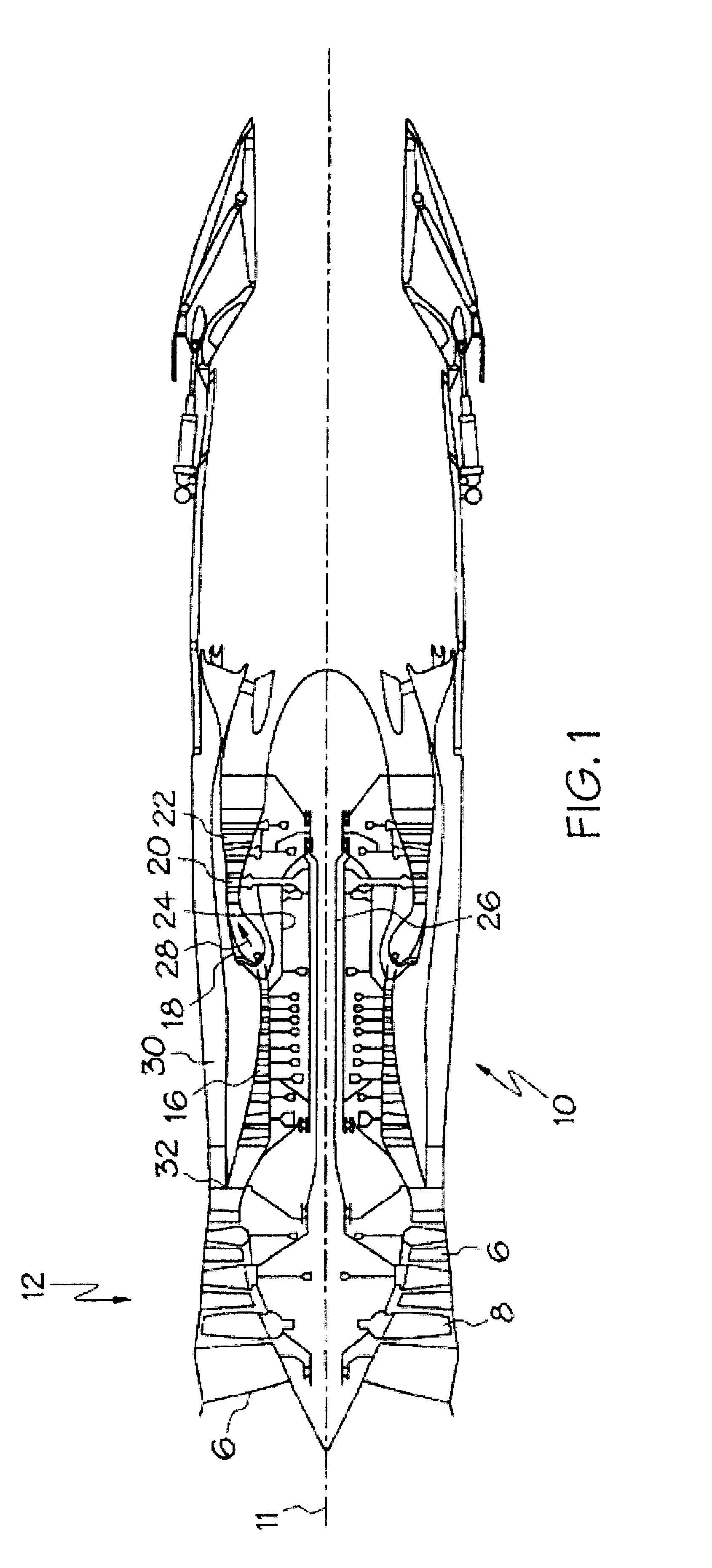
[0022]Referring now to FIG. 1, one example of an aircraft turbofan gas turbine engine is illustrated. While this exemplary turbine engine is shown, it is to be understood that the present invention applies to the repair of airfoil blades associated with the engine of FIG. 1, as well as any other fan, compress...


PUM

PropertyMeasurementUnit
volumeaaaaaaaaaa
displacement-aaaaaaaaaa
shapeaaaaaaaaaa

Abstract

A method for repairing an airfoil comprising creating a nominal numerically-controlled tool path based on a nominal shape of the airfoil, measuring the airfoil using a displacement sensor, capturing differences in the airfoil shape as compared to the nominal shape, creating a three-dimensional map by synchronizing x, y and z coordinates and readings from the sensor, modifying the tool path based on the three-dimensional map, and machining the airfoil. A system for measuring and machining an airfoil comprising a computer operable for data acquisition and numerically-controlled tool path generation, a numerically-controlled machine, a cutting tool holder comprising a plurality of cutting tools, and a displacement-sensing probe.

Description

BACKGROUND OF THE INVENTION[0001]1. Field of the Invention[0002]The present invention relates generally to the field of airfoil repair. More particularly, the present invention relates to systems and methods for measuring airfoil shape to be repaired, comparing the measured airfoil to a nominal shape, and generating a numerically-controlled (NC) tool path to blend a weld-repaired region smoothly with its adjacent surfaces.[0003]2. Description of the Related Art[0004]Airfoils of gas turbine engines are regularly exposed to harsh operating conditions, such as foreign object damage (FOD), high operating temperatures, vibrations and significant pressure fields, as part of normal operating conditions of the engine. For metallic airfoils disposed within an engine, the extreme thermal cycling of normal engine operation represents one of the more deleterious conditions that amplifies the already severe circumstances under which the airfoils must operate. Typically, these operating condition...

Claims


Application Information

Patent Timeline
Patent Type & Authority Patents(United States)
IPC IPC(8): B23Q17/20B23P6/00B23P6/04B23P15/02F01D5/00F01D5/14F01D25/00G06F19/00G05B19/408
CPCB23P6/002B23P6/007G05B19/4083B23K26/3206B23K26/345G05B2219/32228Y10T29/49318G05B2219/45147B23K2201/001G05B2219/35128B23K26/32B23K26/342B23K2101/001B23K2103/50
Inventor WANG, WEIPINGLEE, MARTIN KIN-FEIWEI, BIN
Owner GENERAL ELECTRIC CO
Why Eureka
Try Eureka