
Automatic powder feeding laser induction composite coating method and device

A laser induction, cladding technology, applied in laser welding equipment, heating inorganic powder coating, manufacturing tools, etc., can solve the problems of high coating manufacturing cost, high maintenance cost, loss of cladding layer, etc., to improve the cladding The effect of speed and efficiency, convenient installation and positioning, and short heating time

Active Publication Date: 2008-02-20
WUHAN HIVALUE INTELASER LTD
View PDF0 Cites 80 Cited by
  • Summary
  • Abstract
  • Description
  • Claims
  • Application Information

AI Technical Summary

Problems solved by technology

[0003] However, so far, the application level of laser cladding technology in industry has not reached the early expected goal. The main reasons are: (1) the one-time investment of high-power laser processing equipment is relatively large, and the maintenance cost is expensive; ( 2) The efficiency of laser cladding is much lower than that of traditional processes, such as surfacing and thermal spraying, so the manufacturing cost per unit area of ​​the coating is relatively high; (3) Although laser and thermal spraying can be combined to achieve laser thermal spraying composite cladding technology (J.Suutala, J.Tuominen, P.Vuoristo.Laser-assisted spraying and laser treatment of thermally sprayed coatings, Surface & Coatings Technology, 201(2006): 1981-1987), can improve the efficiency of laser cladding, but due to laser cladding Due to the characteristics of rapid heating, rapid cooling and solidification, and large thermal stress during the process, when laser cladding is performed on the surface of bulk materials, cracks are easily generated in the cladding layer
Especially on the surface of substrates with poor weldability, the problem of cracks has always been the main obstacle for laser cladding processing, which restricts the industrial application of this technology
However, the induction cladding technology has the following disadvantages: (1) The material to be clad needs to be pre-coated on the surface of the substrate, and the cladding preparation workload is relatively large; (2) The melting must be controlled between the liquid-solid two phases, which is prone to melting. The cladding layer is lost, so the compactness of the cladding layer is slightly poor; (3) In the induction cladding process, the maximum temperature that can be reached is limited, so it is difficult to achieve cladding processing for some alloy layers with high melting points; (4) Simple induction Cladding consumes a lot of energy, and it is easy to cause overheating of the substrate, and the product quality is not easy to control

Method used


Image

  • Automatic powder feeding laser induction composite coating method and device
  • Automatic powder feeding laser induction composite coating method and device
  • Automatic powder feeding laser induction composite coating method and device

Examples


example 1

[0052] Example 1: Laser induction composite cladding treatment on the surface of small shaft solid parts

[0053] For small solid shaft parts, the specific implementation method is described by taking a roll with a roll diameter of 325mm as an example. The laser induction composite cladding method for other small shaft solid parts is similar.

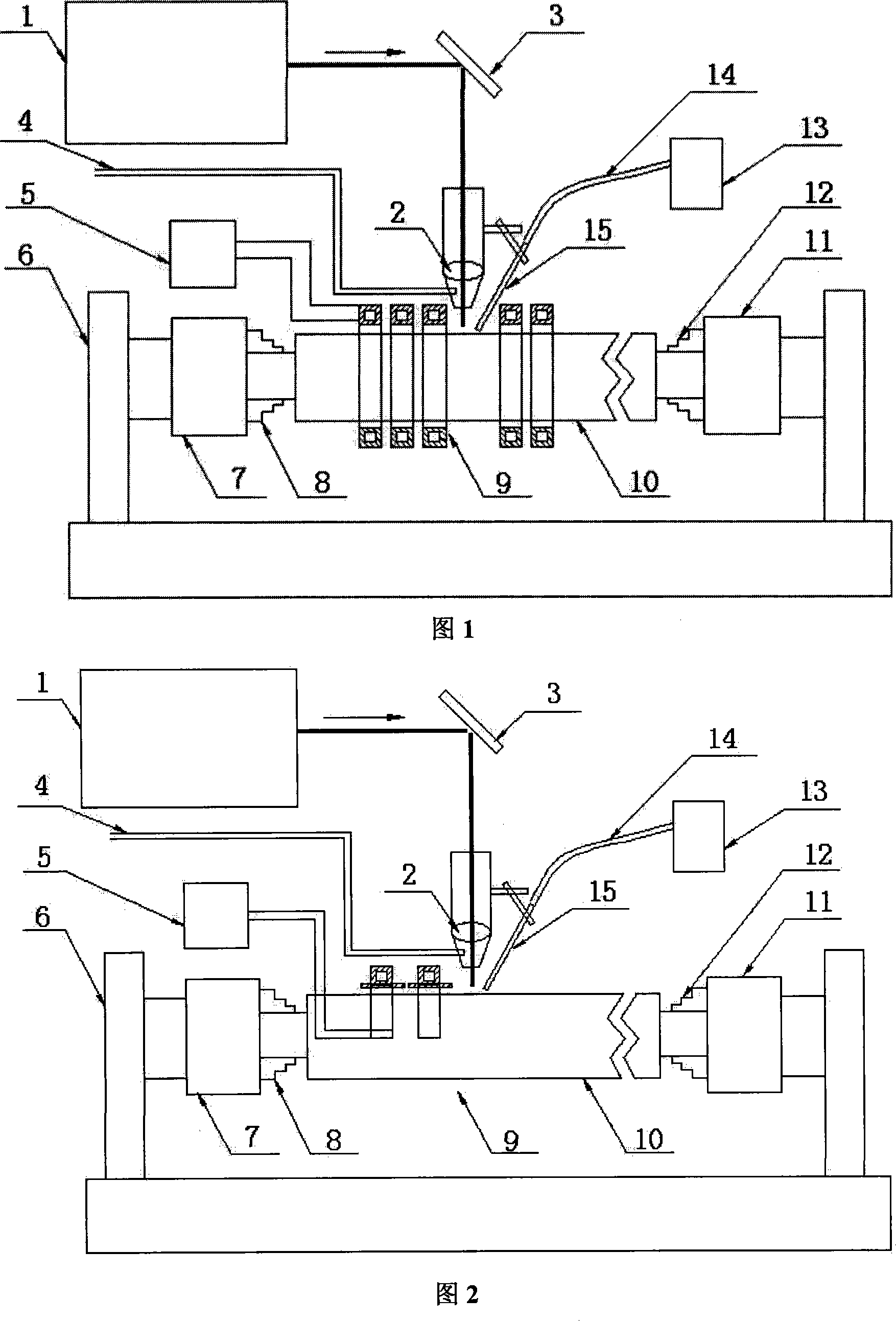
[0054] Using the device shown in Figure 1, the speed is selected according to the diameter of the roll. For a roll with a diameter of 325mm, the speed is set at 0.5-10 rpm, which can be used for rapid cladding strengthening and repairing of solid parts such as rolls.

[0055] The basic steps to implement are as follows:

[0056] (1) Material selection. The cladding material adopts tungsten carbide + nickel-based metal composite material, in which the particle size of tungsten carbide is -140+240 mesh cast tungsten carbide, and the binder phase uses nickel-based self-fluxing alloy Ni60 with a particle size of -140+320 mesh. The tungste...

example 2

[0062] Example 2: Laser induction composite cladding treatment on the surface of large shaft solid parts

[0063] For large shaft solid parts, the specific implementation method is described by taking a roll with a diameter of 650 mm as an example. The laser induction composite cladding treatment method for the surface of other large shaft solid parts is similar.

[0064] Using the device shown in Figure 2, the rotation speed is selected according to the size of the roll diameter, mainly to ensure that the linear speed during laser processing is within the required range. For rolls with a roll diameter of 650mm, the speed is set at 0.3-5 rpm, which can be used for rapid cladding strengthening and repairing of solid parts such as large rolls.

[0065] The basic steps to implement are as follows:

[0066](1) Material selection. The cladding material adopts tungsten carbide + nickel-based metal composite material, in which the particle size of tungsten carbide is -140+240 mesh ...

example 3

[0072] Example 3: Laser Induction Composite Cladding Treatment on the Outer Wall of Tubular Parts

[0073] For tubular components, a pipe with an outer diameter of 108 mm and a wall thickness of 5 mm is used as an example for illustration. The laser induction heating composite cladding treatment method for the outer surface of other tubular components is similar.

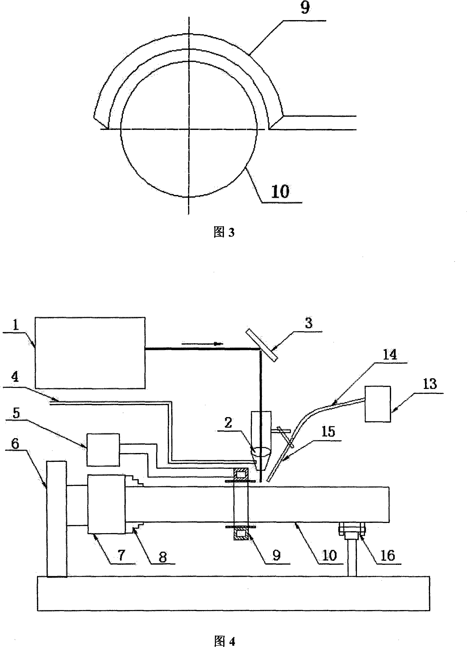
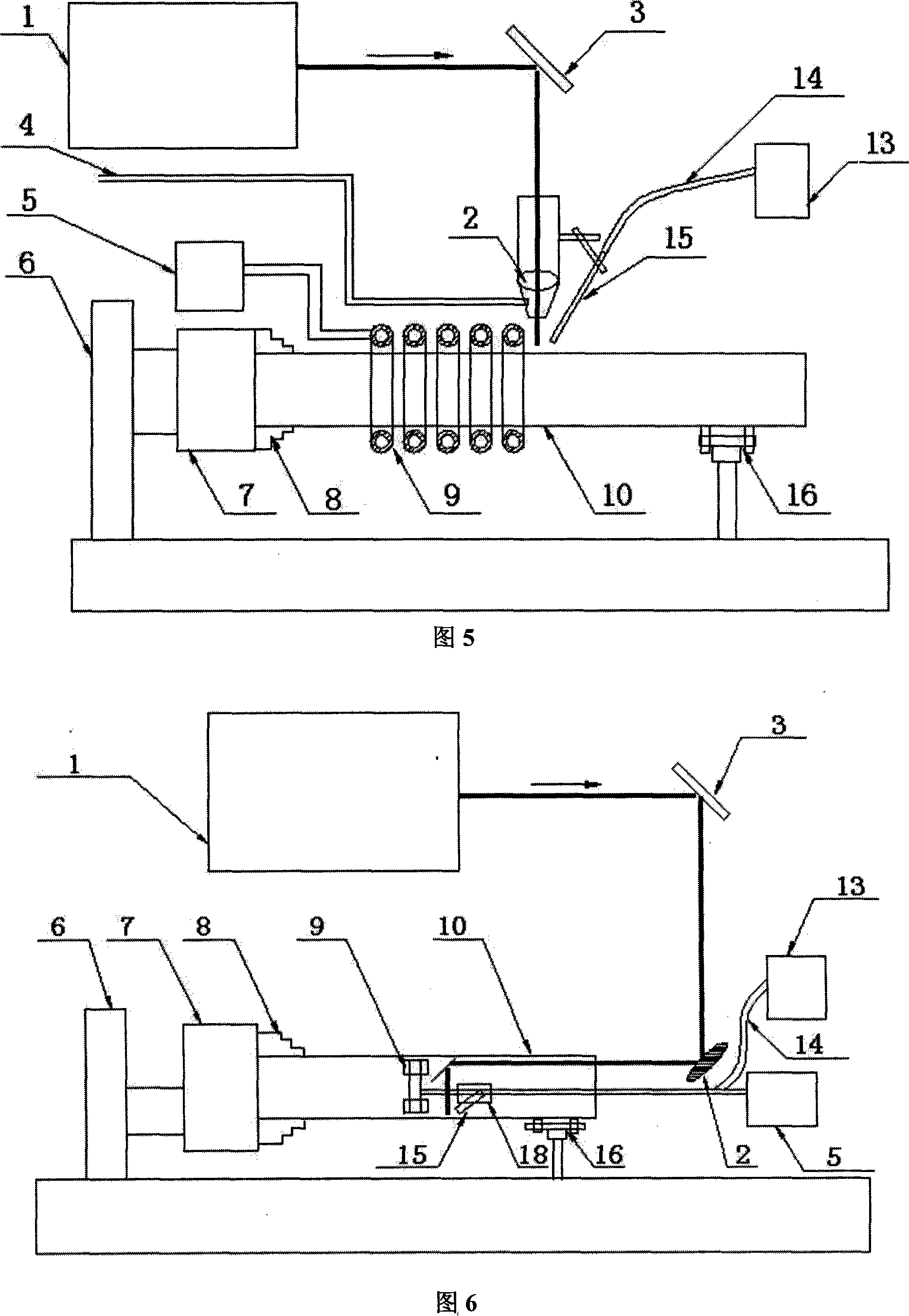
[0074] Adopt the device as shown in Figure 4, its implementation basic steps are as follows:

[0075] (1) Material selection. The cladding material adopts tungsten carbide + nickel-based metal composite material, in which the tungsten carbide particle size is -140+240 mesh cast tungsten carbide, and the binder phase uses nickel-based self-fluxing alloy Ni45 with a particle size of -140+320 mesh. The tungsten carbide is evenly mixed with the nickel-based self-fluxing alloy, and the mass percentage of the tungsten carbide is 60%. The substrate is made of low carbon steel pipe.

[0076] (2) The distance between the ...


PUM

PropertyMeasurementUnit
thicknessaaaaaaaaaa
particle sizeaaaaaaaaaa
thicknessaaaaaaaaaa

Abstract

The present invention discloses a laser induced composite cladding measure and device for the automatic powder feeder. The present invention couples the laser beam and the high frequency electromagnetic induction heating so as to realize the composite cladding between the laser and the induction heating. The device comprises a laser, a laser light guide device, a laser gathering system, a high frequency induction heater, a digital control machine tool and a workpiece holding device. In work, the distance between the surface of workpiece under treatment and the induction heating coil is 1 to 10 mm. The present invention has a strong commonality and can conduct surface treatment of laser induced composite cladding high performance material coat toward the surface of the solid components in various materials and the inner and outer surfaces of the tubular spare parts. The cladding measure is characterized in that: the high frequency induction heater heats up the workpieces simultaneously and the automatic power feeder is applied to deliver the cladding powder to the laser irradiation area on the surface of the workpiece, so the alloy powder is instantaneously melted under the action of laser beam to form an alloy layer; and the maximum cladding speed reaches 10 m / min and the cladding efficiency is improved by one to ten times than the regular laser cladding and the powder utilization rate exceeds 90 percent; the applicable cladding materials have a wide range, comprising various wear resistant, corrosion resistant materials or high temperature resistant oxidizing materials as well as the composite materials; moreover, the cladding layer has no pores and crackles.

Description

technical field [0001] The invention belongs to the technical field of laser processing, and in particular relates to an automatic powder feeding laser induction composite cladding method and a device thereof. Background technique [0002] Laser cladding technology is a process of cladding a layer of material with special properties on the surface of a workpiece by using a high-energy-density laser beam to improve its surface properties. Compared with the traditional surfacing and thermal spraying process, the laser cladding technology has the following advantages: (1) The energy density of the laser beam is high, and the heat-affected zone and thermal deformation of the workpiece can be minimized during the cladding process; ( 2) By adjusting the process parameters, a cladding layer with a dilution rate of less than 10%wt can be obtained; (3) The cladding layer forms a metallurgical bond with the base material, which has high bonding strength and is not easy to peel off; (4...

Claims


Application Information

Patent Timeline
Patent Type & Authority Applications(China)
IPC IPC(8): B23K26/34C23C24/08
Inventor 曾晓雁胡乾午黄永俊周圣丰
Owner WUHAN HIVALUE INTELASER LTD
Learn More