

Interference fit type cutting tool
a cutting tool and interfacial technology, applied in the direction of tool workpiece connection, shaping cutter, manufacturing tools, etc., can solve the problems of low rigidity of materials with a high coefficient of thermal expansion and apt to suffer chatter vibration, and achieve the effect of low chatter vibration and high stiffness
- Summary
- Abstract
- Description
- Claims
- Application Information
AI Technical Summary
Benefits of technology
Problems solved by technology
Method used
Image

Examples
first embodiment
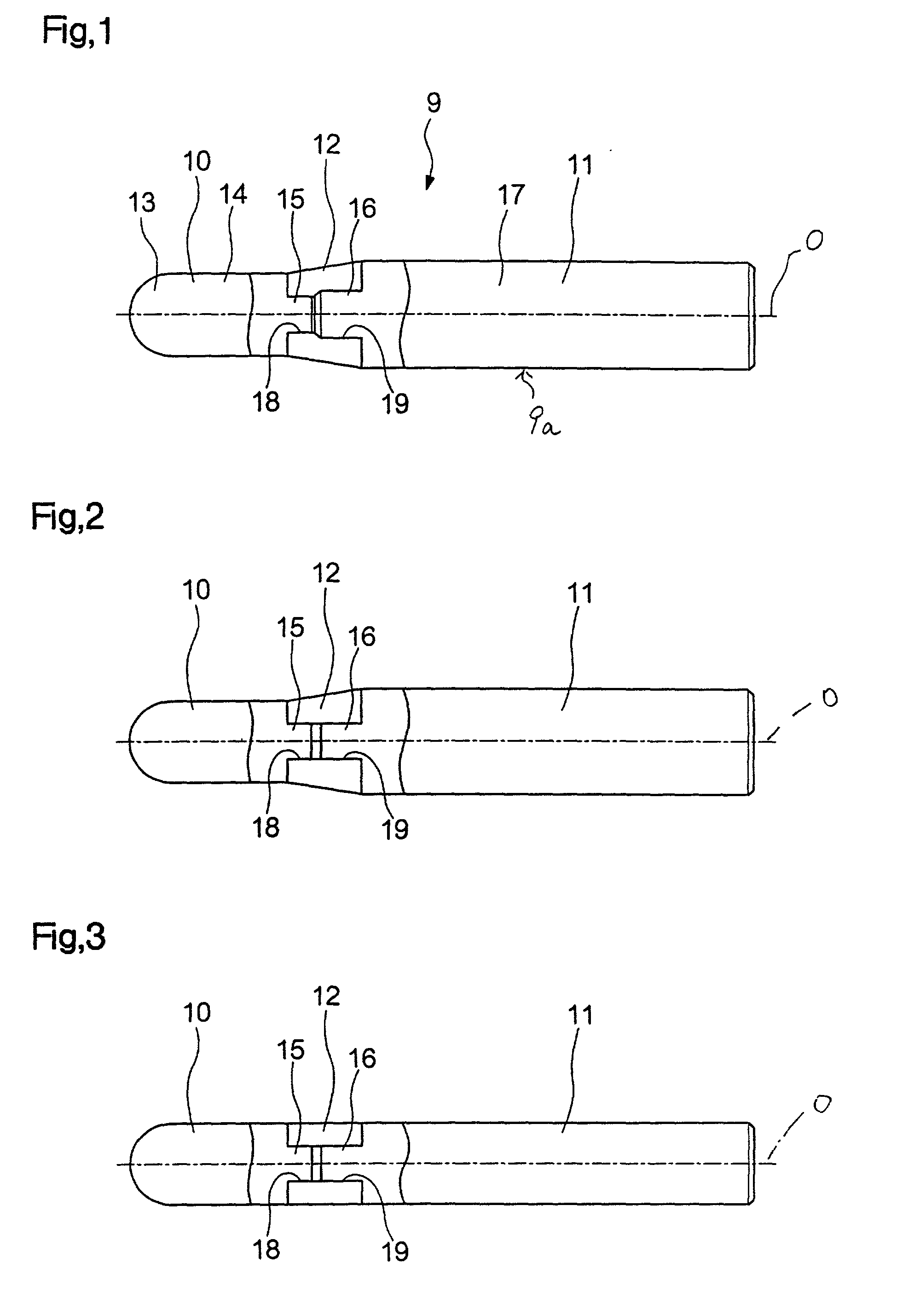
[0044] the present invention will be described below with reference to FIG. 1.
[0045] A tool body 9a of a ball endmill 9 shown in FIG. 1 comprises an edge section 10, a shank section 11, and a connecting member 12 for connecting these sections in the direction of the axis O.
[0046] The edge section 10 is made of, for example, cemented carbide, and is composed of a substantially hemispherical leading end portion 13, a substantially cylindrical shaft portion 14 that is coaxial with the axis O, and a projection 15, which are disposed in that order from the leading end toward the base end (rear end) in the direction of the axis O.
[0047] The leading end portion 13 is a portion that is directly used for cutting, and is provided with a cutting edge (not shown) having, for example, substantially a 1 / 4-arc shape. The projection 15 is a portion that serves to make connection with the connecting member 12, has a diameter appropriately smaller than that of the shaft portion 14, and is coaxially f...
third embodiment
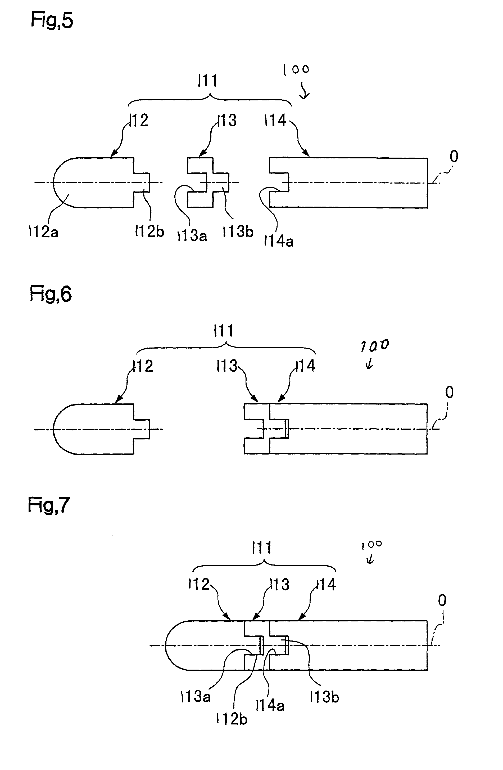
[0070] Next, the present invention will be described with reference to FIGS. 5 to 7.
[0071] In these figures, numerals 111, 112, 113, and 114 denote a tool body, an edge section, a connecting member, and a shank section, respectively. The tool body 111 of a ball endmill 100 is mainly composed of the edge section 112, the shank section 114, and the connecting member 113 for connecting these sections along the axis O of the tool body 111.
[0072] The edge section 112 is made of, for example, cemented carbide. At the base end of the edge section 112, a cylindrical projection 112b is formed to make connection with the connecting member 113. The projection 112b extends along the axis O, and the outer diameter and length thereof are set at appropriate values. The connecting member 113 is made of a material having a higher coefficient of thermal expansion than those of the edge section 112 and the shank section 114, e.g., steel. A fitting recess 113a to be connected to the projection 112b of ...
fourth embodiment
[0082] While the projection 112b is formed at the base end of the edge section 112 and the recess 114a is formed at the leading end of the shank section 114 in the ball endmill 100 of the above-described embodiment, a recess 131a may be formed at the base end of an edge section 131, a projection 132a may be formed at the leading end of a shank section 132, and a connecting member 113 having the same structure as described above may be interposed between the edge section 131 and the shank section 132 in the position longitudinally reverse to that shown in FIG. 5, as in a ball endmill 150 shown in FIGS. 8 to 10.
[0083] While the edge sections 10, 112, and 131 and the shank sections 11, 21, 114, and 132 are made of cemented carbide in the above-described first to fourth embodiments, the edge sections 10, 112, and 131 may be made of cermet, high-speed steel, or the like, and the shank sections 11, 21, 114, and 132 may be made of cermet, high-hardness sintered material, or the like. The ...
PUM
 Abstract
Description
Claims
Application Information