Wind power generating device

Inactive Publication Date: 2001-11-01
MITSUBISHI ELECTRIC CORP
View PDF0 Cites 90 Cited by
  • Summary
  • Abstract
  • Description
  • Claims
  • Application Information

AI Technical Summary

Problems solved by technology

However, because the conventional wind power generating device has the above-described cooling structure, a part of the driving power obtained from the wind power in the blades 3 is consumed by the air blower.
Therefore, there is a problem that an energy generation efficiency is lowered in the conventional wind power generating device.
Also, in the conventional wind power generating device having the above-described cooling structure, even though the structure of the air supplying opening 10 and exhaust vents 11 is skillfully designed, it is difficult to remove water and / or salt contained in the outside air, and the outside air containing water and / or salt is undesirably supplied into the nacelle 2.
Therefore, it is difficult to completely prevent the units placed in the nacelle 2 from being corroded by the water and / or salt contained in the outside air, and there is a problem that corrosion treatment is required for the units other than the closed type generator 5.
Also, because each exhaust vent 11 is formed in the labyrinth structure, there is another problem that the structure of the nacelle 2 is complicated.
Also, the wind power generating device does not have an air supplying opening, an exhaust vent or an air blower used in the prior art.

Method used


Image

  • Wind power generating device
  • Wind power generating device
  • Wind power generating device

Examples


first embodiment

[0089] A wind power generating device which differs from that of the prior art, has no step-up gear. However, the present invention can be applied for a wind power generating device with a step-up gear.

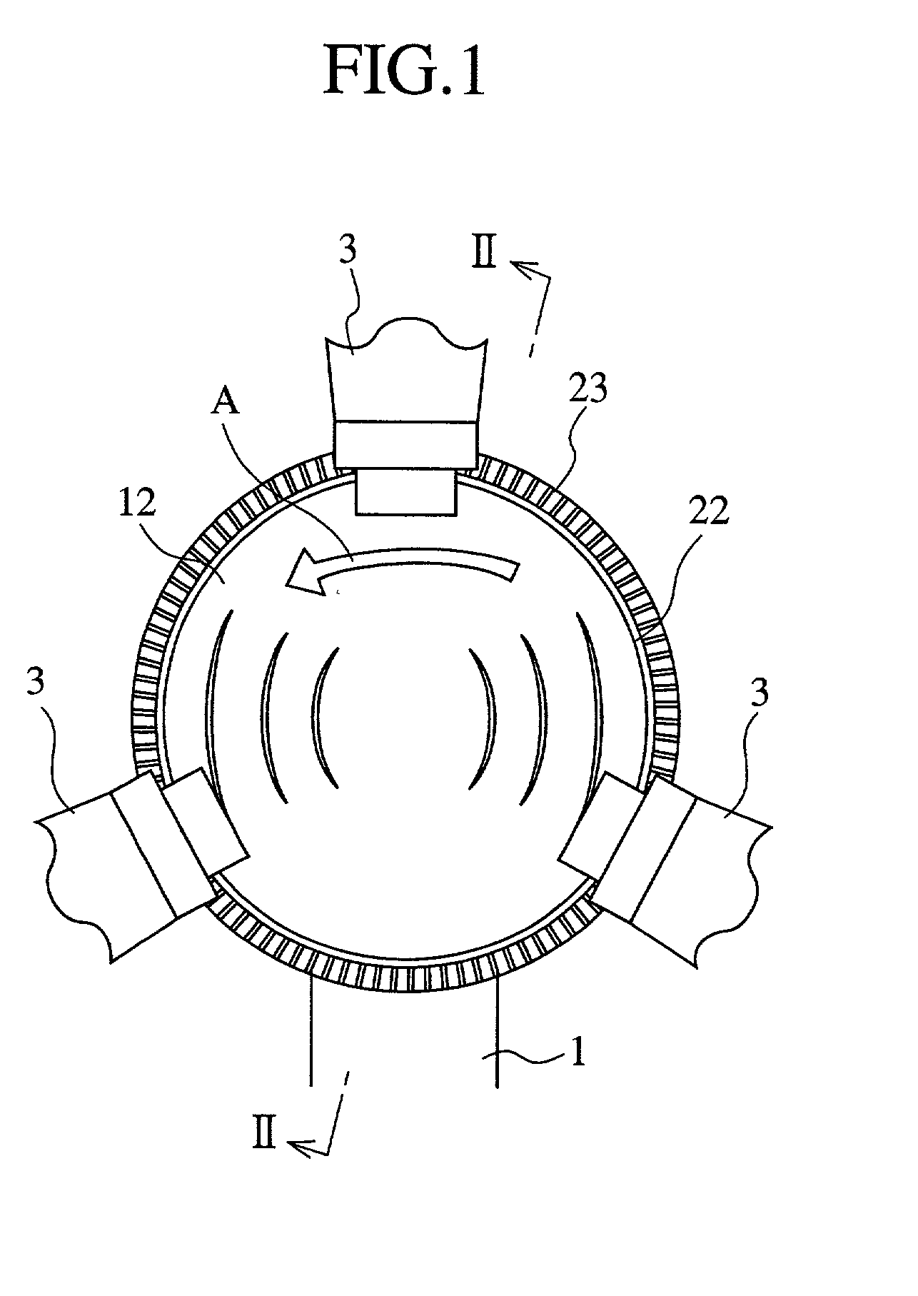
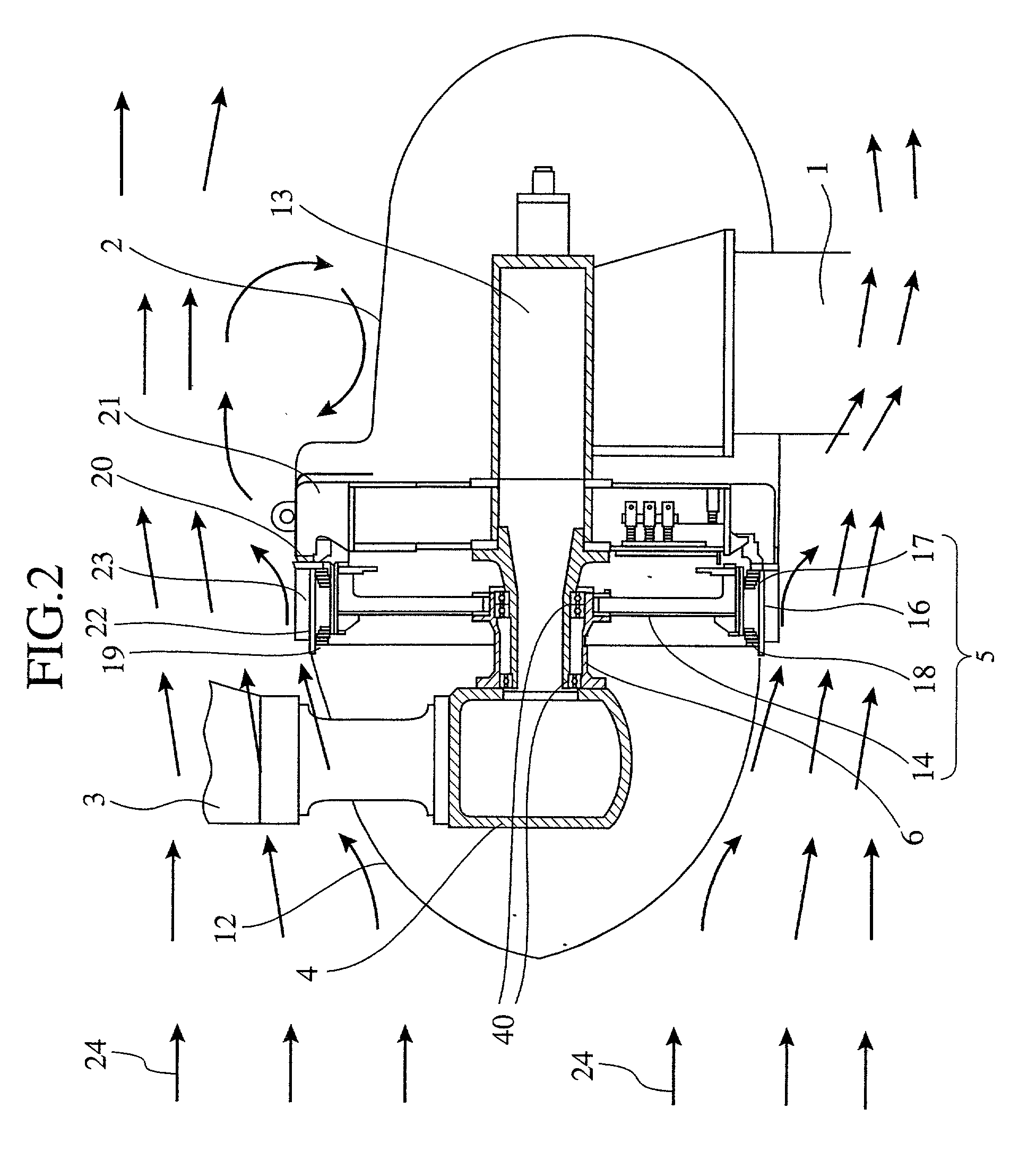
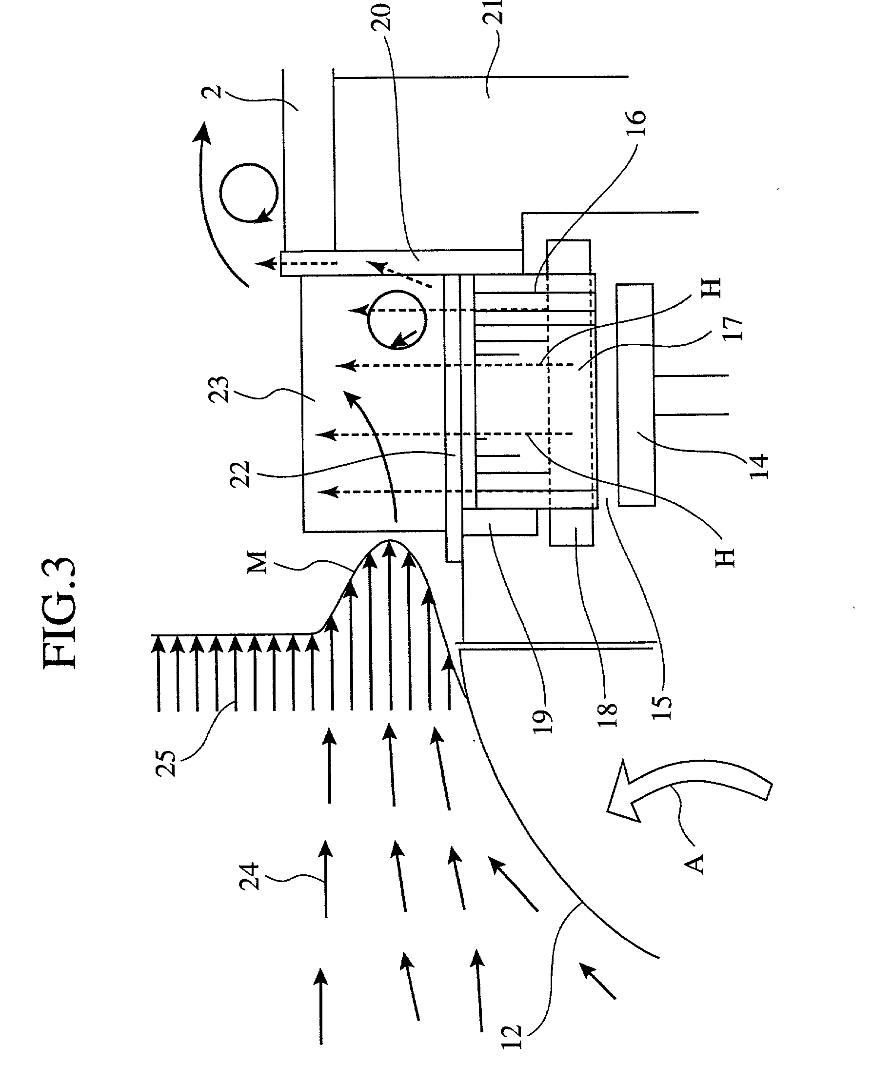
[0090] In the first embodiment, as shown in FIG. 1, FIG. 2 and FIG. 3, the hub 4, to which the three blades 3 receiving wind are fixed so as to extend in a radial direction of the hub 3 at equal intervals, is arranged in a spindle-shaped boss 12. The spindle-shaped boss 12 has an air flow direction rectifying function. The hub 4 is fixed to the front portion (or a windward-side portion) of the horizontal shaft 6. A longitudinal direction of the horizontal shaft 6 is controlled by an anemoscope & anemometer (not shown) and a direction control mechanism (not shown) operated with each other to always arrange the hub 4 and the blades 3 on the windward side of the horizontal shaft 6. The horizontal shaft 6 is attached to a fixed shaft 13 through a bearing 40 and rotates freely on the fixe...

embodiment 2

[0100] FIG. 5 is a diagonal view, with portions broken away for clarity, of a plurality of heat dissipating units of a wind power generating device according to a second embodiment of the present invention.

[0101] As shown in FIG. 5, in a wind power generating device according to a second embodiment, a plurality of divided fins (or heat dissipating units), each of which is outwardly protruded in the radial direction of the frame 22 and extends along the axial direction of the frame 22 (or a wind direction), are arranged on the outer peripheral surface of the frame 22 so as to be placed at equal intervals in the circle-circumferential direction of the frame 22, the divided fins are classified into a plurality of groups of divided fins (three groups of divided fins in this embodiment) serially placed in the axial direction of the frame 22, and each pair of divided fins adjacent to each other in the axial direction of the frame 22 are placed at positions different from each other along ...

embodiment 3

[0107] FIG. 6 is a diagonal view, with portions broken away for clarity, of a plurality of heat dissipating units of a wind power generating device according to a third embodiment of the present invention.

[0108] As shown in FIG. 6, in a wind power generating device according to a third embodiment, a plurality of pins are arranged in place of the divided fins 23a, 23b and 23c of the second embodiment. More precisely, a plurality of columnar pins (or heat dissipating units) 26a, 26b and 26c, each of which is outwardly protruded in the radial direction of the frame 22, are arranged on the outer peripheral surface of the frame 22 so as to place the group of pins 26a at the first row from the windward side, to place the group of pins 26b at the second row and to place the group of pins 26c at the third row. Each pair of pins 26a and 26b adjacent to each other in the axial direction of the frame 22 are placed at positions different from each other in the circle-circumferential direction o...


PUM


Abstract

A hub, to which three blades 3 receiving wind are fixed so as to extend in a radial direction of the hub at equal intervals, is arranged in a spindle-shaped boss having a rectification function. A cylindrical frame is arranged on the leeward side of the boss to separate an outer peripheral surface of a generator from outside air. An outer surface of the boss, which rotates with the blades, and an outer peripheral surface of the frame form a continuous plane. On the outer peripheral surface of the frame, a plurality of fins, which are outwardly protruded in a radial direction of the frame and extend in an axial direction of the frame, are arranged in a circle-circumferential direction of the frame at equal intervals. After the outside air gives a rotational force to the blades, the outside air passes along the fins. Therefore, heat, which is generated in the generator and is transferred to the fins through the frame by conduction, is dissipated to the outside air. Accordingly, the temperature of the generator can be reliably maintained to a value equal to or lower than a standard value, and a wind power generating device having a simple cooling structure can be manufactured.

Description

[0001] 1. Field of the Invention[0002] The present invention relates to a wind power generating device having a cooling structure.[0003] 2. Description of Related Art[0004] In a general wind power generating device, it is required to maintain the reliability of the device by efficiently dissipating heat generated in an electric power generator of the device to the outside and by decreasing a temperature of the generator (or an internal temperature of the device) to a prescribed allowable temperature or below. Therefore, in a conventional wind power generating device with a closed type generator, an air blower is attached to a horizontal shaft to which a plurality of blades receiving wind power are fixed, outside air is supplied into the wind power generating device through an air supplying opening by using the air blower, and the generator functioning as a heat generating unit is cooled.[0005] A conventional wind power generating device having the above-described cooling structure w...

Claims


Application Information

Patent Timeline
IPC IPC(8): F03D11/00
CPCF03D11/00F05B2260/20Y02E10/722Y02E10/725H02K7/1838F03D9/25F03D80/60Y02E10/72Y02P70/50
Inventor UMEMOTO, TOSHIYUKIIKEDA, YUJINAGATANI, RYOJIKOTOH, SATORU
Owner MITSUBISHI ELECTRIC CORP
Why Eureka
Try Eureka