Sensing system for detecting presence of an ink container and level of ink therein

a technology of ink supply container and sensor system, which is applied in the direction of liquid/fluent solid measurement, instruments, machines/engines, etc., can solve the problems of damage to the associated printhead, no prior art reference includes means, and the reliance on prior art references is relatively high

Inactive Publication Date: 2001-11-01
SAMSUNG ELECTRONICS CO LTD
View PDF0 Cites 187 Cited by
  • Summary
  • Abstract
  • Description
  • Claims
  • Application Information

AI Technical Summary

Benefits of technology

[0017] Another object of the invention is to provide an ink supply container which is constructed so as to enable an inexpensive optical detection system which performs both the ink container detection as well as the low ink level detection function.

Problems solved by technology

Printer operation with the container removed could potentially damage the associated printhead.
Some of the prior art references are relatively expensive relying on measurement and detection of ink conductivity or drop detecting circuitry.
Further, none of the prior art references includes means for insuring that the ink tank is in proper position before beginning the ink level sensing operation.

Method used


Image

  • Sensing system for detecting presence of an ink container and level of ink therein
  • Sensing system for detecting presence of an ink container and level of ink therein
  • Sensing system for detecting presence of an ink container and level of ink therein

Examples


Embodiment Construction

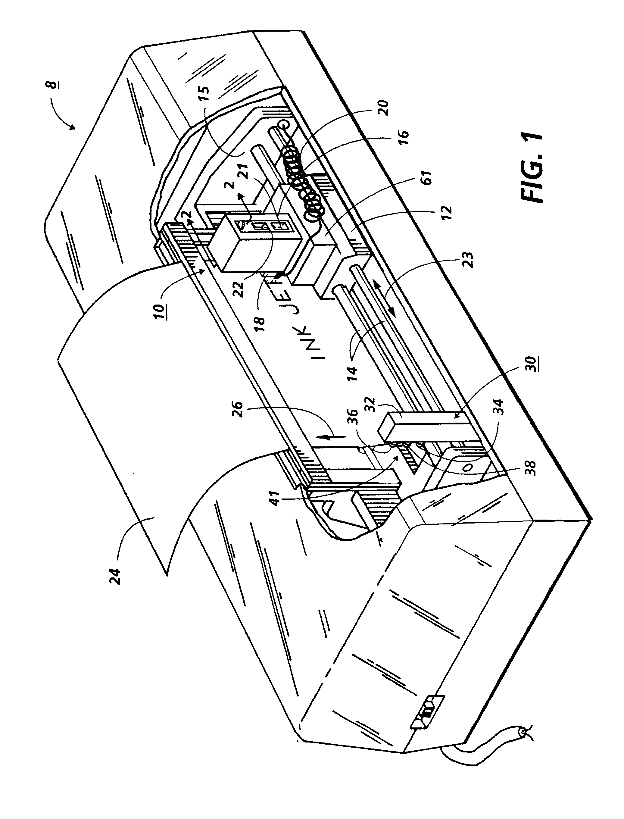
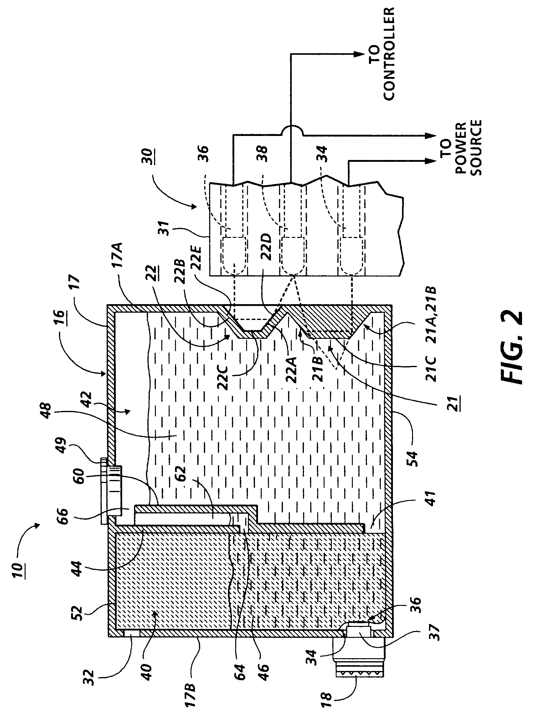
[0049] FIG. 1 illustrates a perspective view of a thermal ink jet printer 8 which incorporates a preferred embodiment of the ink container and low ink detection system of the present invention. Printer 8 is exemplary only. The invention can be practiced in other types of thermal ink jet printers as well as other reproduction devices such as piezoelectric printers, dot matrix printers and ink jet printers driven by signals from a document Raster Input Scanner. Printer 8 includes an ink jet printhead cartridge 10 mounted on a carriage 12 supported by carriage rails 14. The carriage rails are supported by a frame 15 of the ink jet printer 8. The printhead cartridge 10 includes a container 16 shown in detail in FIG. 2, containing ink for supply to a thermal ink jet printhead 18 which selectively expels droplets of ink under control of electrical signals received from a controller 50 (FIG. 4) of the printer 8 through an electrical cable 20. Container 16 comprises a housing 17 having a wa...


PUM


Abstract

A low ink sensing system is combined with an ink cartridge detection system to enable a more efficient ink jet printer. An ink container which supplies ink to an associated printhead is modified by the incorporation of two light directing elements, in the preferred embodiment, a faceted prism and a roof mirror, into a transparent wall of the container housing. The cartridge, comprising the ink container and associated printhead, is mounted on a scan carriage. Periodically, the carriage is conveyed to a sensing station comprising a pair of light sources and a commonly used photosensor. A first light source is energized and a beam of light is directed to a location where the roof mirror, would be positioned if the cartridge is present. If the cartridge is absent, lack of a reflected return signal is sensed, indicating a cartridge has not been inserted. Print operation is halted until a cartridge is inserted. If a cartridge is properly inserted, the roof mirror returns most of the incident light to the photosensor which generates a signal indicating the presence of the cartridge. A second light source is then energized and directed towards the faceted prism, which is either immersed in ink or exposed to air within the interior of the container. If the latter, light is internally reflected by the prism facets back to the photosensor. If a print operation has been in progress, and the ink level has fallen, the common photosensor detects either a strong or weak redirected light component and initiates a status check and generates appropriate displays of low ink level or out of ink warnings.

Description

BACKGROUND AND MATERIAL DISCLOSURE STATEMENT[0001] The present invention relates to ink jet recording devices and, more particularly, to a system for detecting the presence of an ink supply container and also for detecting when the level of ink in the container is at or below a predetermined level.[0002] Ink jet recording devices eject ink onto a print medium such as paper in controlled patterns of closely spaced dots. To form color images, multiple groupings of ink jets are used, with each group being supplied with ink of a different color from an associated ink container.[0003] Thermal ink jet printing systems use thermal energy selectively produced by resistors located in capillary filled ink channels near channel terminating nozzles or orifices to vaporize momentarily the ink and form bubbles on demand. Each temporary bubble expels an ink droplet and propels it toward a recording medium. The printing system may be incorporated in either a carriage type printer or a pagewidth typ...

Claims


Application Information

Patent Timeline
Patent Type & Authority Applications(United States)
IPC IPC(8): B41J2/125B41J2/175G01F23/28G01F23/292
CPCB41J2/17513B41J2/17546B41J2/17553B41J2/17566B41J2002/17569B41J2002/17573G01F23/2922G01F23/2927
Inventor ALTFATHER, KENNETH W.CARLOTTA, MICHAELDIETL, STEVEN J.STEVENS, DONALD M.HUBBLE, FRED F. III
Owner SAMSUNG ELECTRONICS CO LTD
Why Eureka
Try Eureka