Material removing tool

a technology of material removal and tool, which is applied in the direction of metal sawing equipment, gear teeth, stone-like material working equipment, etc., can solve the problems of not being able to form precisely defined and not being suited to the making of accurate laterally limited and definable recesses or grooves in workpieces

Inactive Publication Date: 2001-11-15
C & E FEIN GMBH & CO KG
View PDF11 Cites 51 Cited by
  • Summary
  • Abstract
  • Description
  • Claims
  • Application Information

AI Technical Summary

Benefits of technology

0005] It is an object of the present invention to provide an apparatus or implement which can employ a material removing (such as a cutting and / or grinding) tool that is more versatile than heretofore known apparatus of such character.

Problems solved by technology

While the just described tools can be put to many uses, they are not suited for the making of accurate laterally limited and definable recesses or grooves in a workpiece.
Since oscillating grinders execute rotary movements, they cannot be used to form precisely defined recesses or grooves.

Method used


Image

  • Material removing tool
  • Material removing tool
  • Material removing tool

Examples


Embodiment Construction

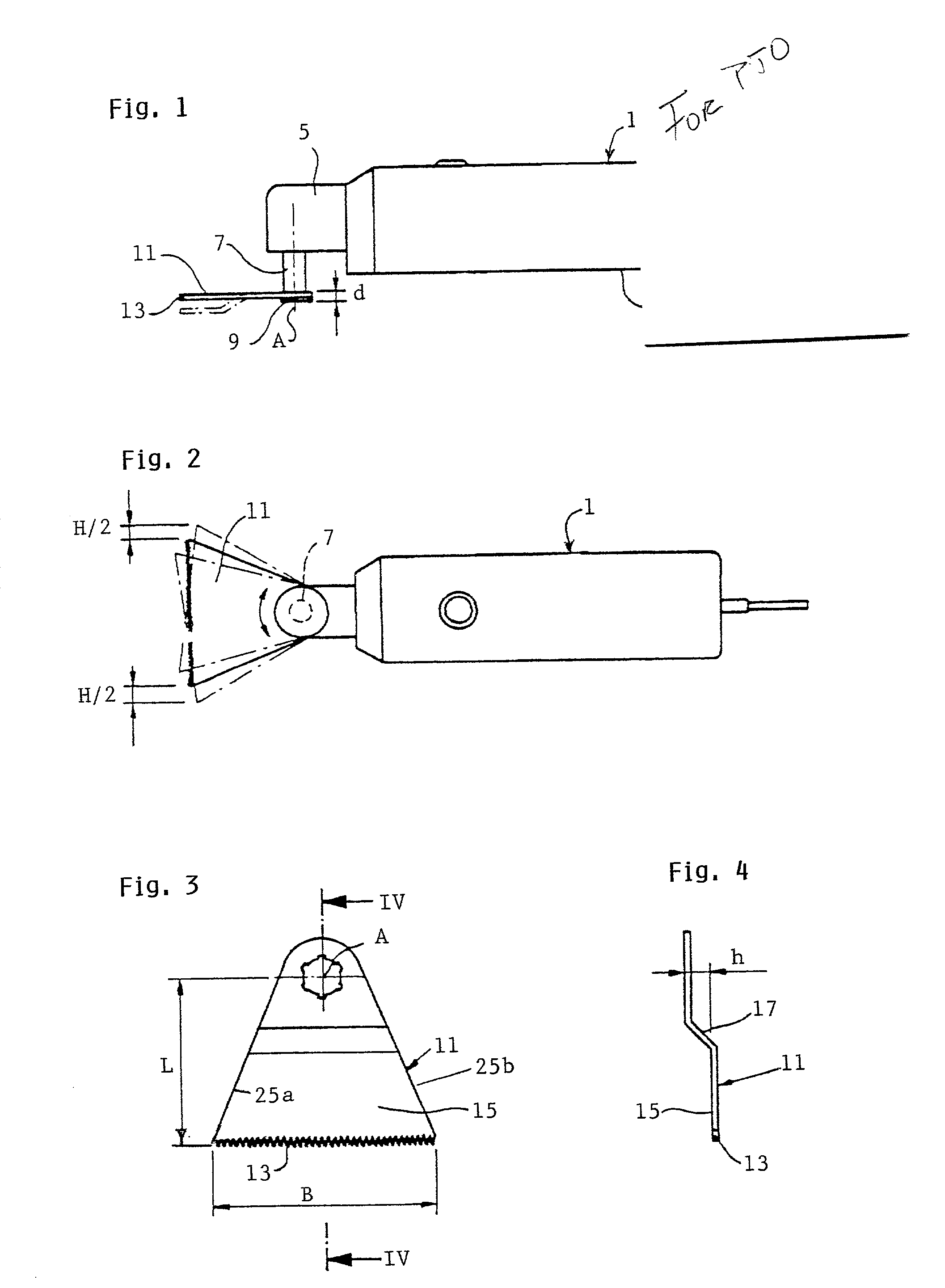
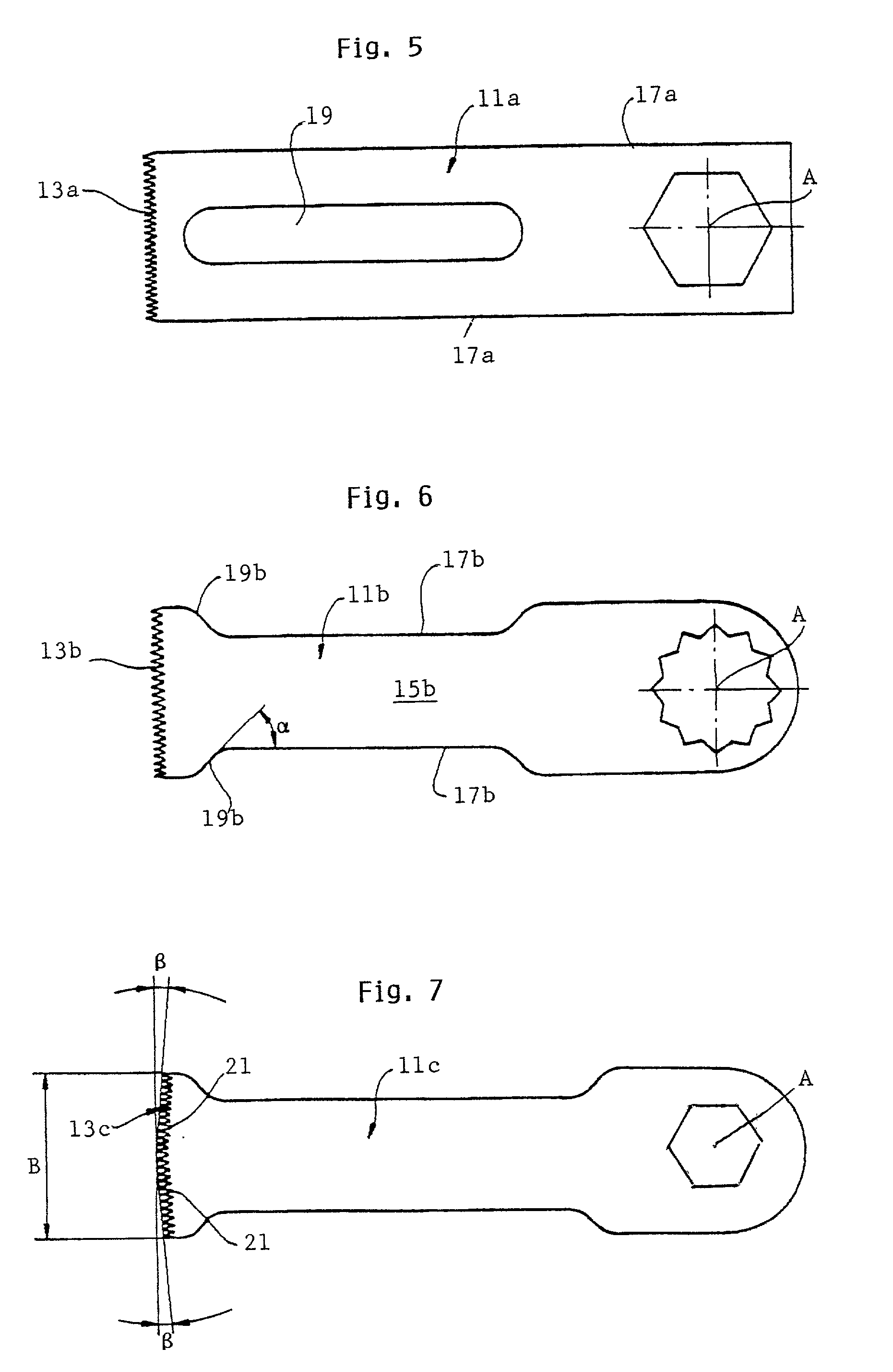
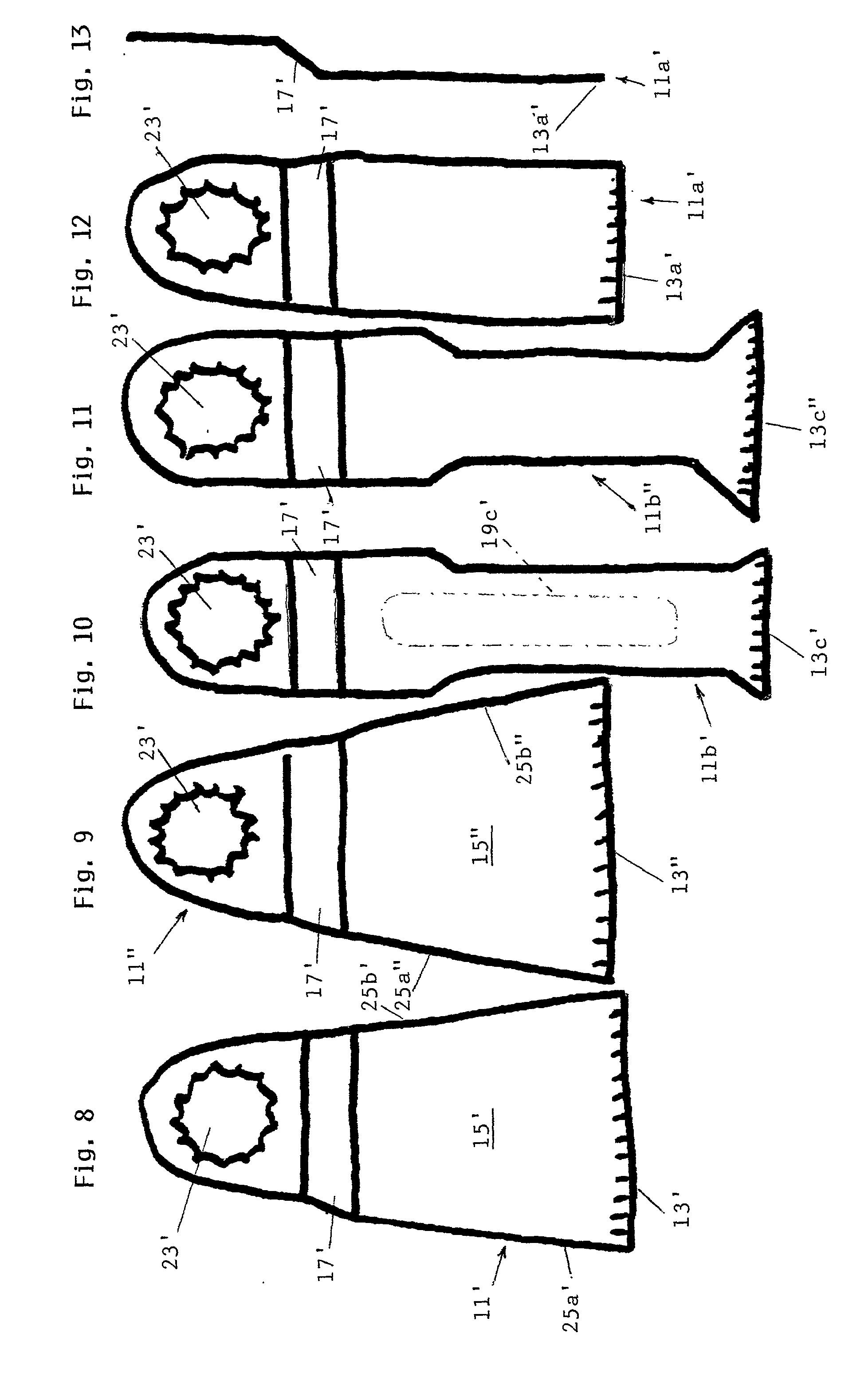
[0040] The motor-driven and manually operable implement or apparatus 1 depicted in FIG. 1 is provided with a housing including a handle 3 confining a prime mover (not shown) and a section 5 for a transmission (also not shown). The transmission is provided with an output shaft 7 extending outwardly from the housing section 5. At the free end of the shaft 7, there is provided a suitable tool fastening means, such as a chuck or a bolt 9, for rigidly attaching to the shaft a material removing tool 11. For example, the prime mover may constitute an electric or a fluid-operated (such as pneumatic) motor. The output shaft 7 is assumed to be adapted to execute oscillatory movements abut an axis A within a range of about two angular degrees and at a frequency which can be infinitely adjustable between zero and 20,000 cycles per minute.

[0041] One end section of the tool 11 is provided with a cutting edge 13 defined by numerous teeth. As used herein, the term "cutting edge" is intended to embr...


PUM

PropertyMeasurementUnit
acute angleaaaaaaaaaa

Abstract

A material removing tool, such as a cutting or grinding tool, adapted to be oscillated by the output shaft of a manually operable motor-driven apparatus, is provided with at least one elongated cutting edge defined by teeth or analogous cutting elements arranged in at least one at least substantially straight linear array.

Description

[0001] The present invention relates to improvements in apparatus of the kind in which a material removing tool is arranged to move relative to a workpiece, and more particularly to improvements in apparatus in which a material removing tool (such as a cutting or grinding tool) is arranged to be mounted on a motor-driven output shaft and carry out oscillatory movements when in actual use.[0002] Prior art is replete with disclosures of apparatus or implements which are provided with material removing tools arranged to be mounted on the output shafts of the apparatus and being adapted to execute oscillatory movements. In many instances, the oscillatory movement involves a back-and-forth movement through about two angular degrees at a frequency of about 20,000 oscillations per minute. Such conventional apparatus may be designed for numerous applications, or they are constructed for specific applications. Many conventional apparatus are used to remove, without causing damage, bonded win...

Claims


Application Information

Patent Timeline
Patent Type & Authority Applications(United States)
IPC IPC(8): B23D61/12B28D1/12
CPCB23D61/006B23D61/12B23D61/123B28D1/127Y10T83/8798Y10T83/9454
Inventor STEIGER, MARCOSUTER, DAVID
Owner C & E FEIN GMBH & CO KG
Why Eureka
Try Eureka