Stent for in-stent restenosis

a technology for restnosis and stents, which is applied in the field of restnosis stents, can solve the problems of stenosis that can be life-threatening, reduce the flow of blood to the heart, and affect the function of the stent, and achieve the effect of reducing the severity of restnosis

Inactive Publication Date: 2001-11-22
BOSTON SCI SCIMED INC
View PDF51 Cites 111 Cited by
  • Summary
  • Abstract
  • Description
  • Claims
  • Application Information

AI Technical Summary

Benefits of technology

0022] The inventive methods may be preceded and/or followed by one or more...

Problems solved by technology

Regardless of the cause of the stenosis, a stenosis can be life threatening.
Stenoses of coronary arteries, for example, can diminish the...

Method used


Image

  • Stent for in-stent restenosis
  • Stent for in-stent restenosis
  • Stent for in-stent restenosis

Examples


Embodiment Construction

in its various embodiments is provided below.

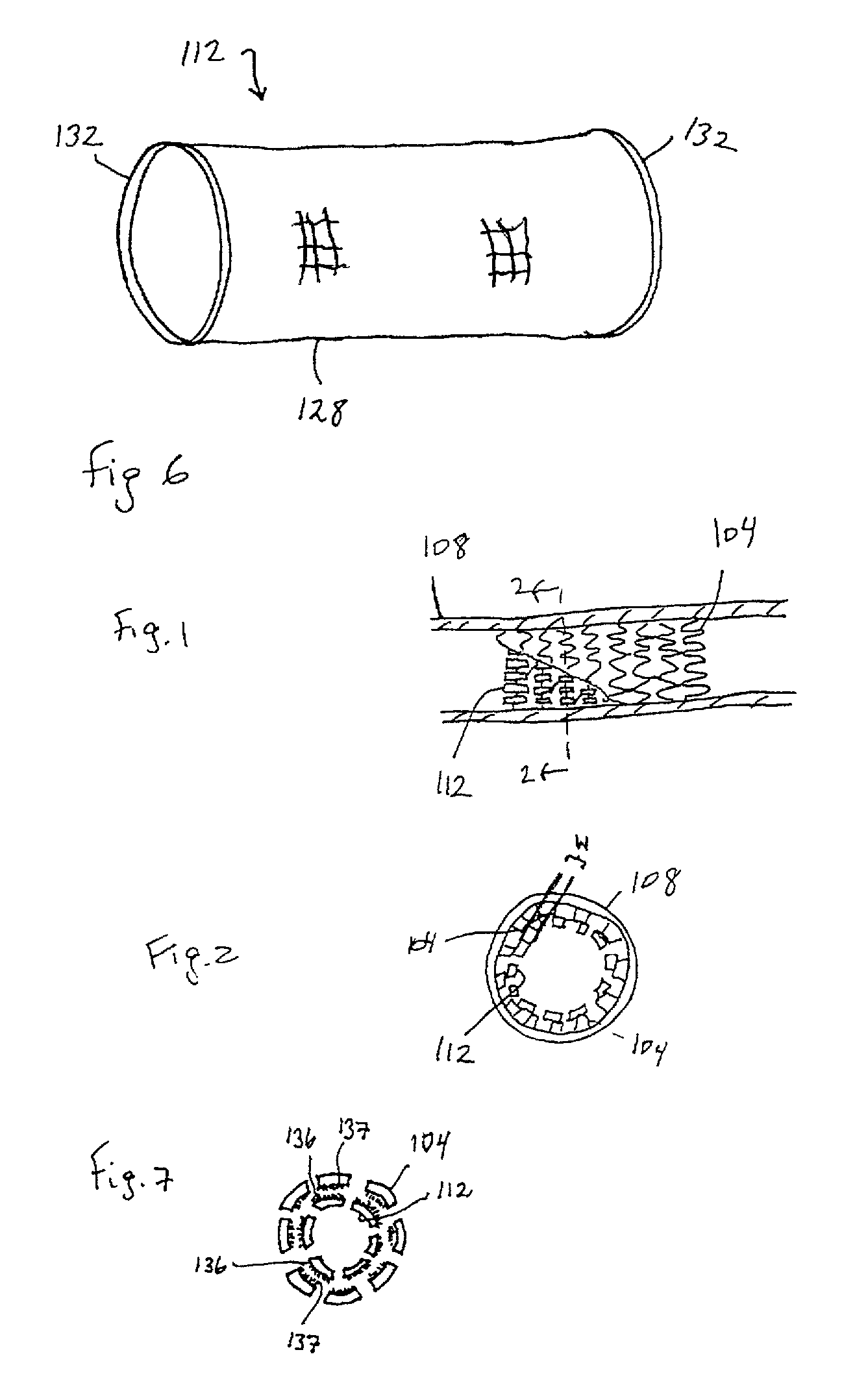
[0024] FIG. 1 shows a perspective view of the inventive stent combination in a vessel with parts cut away.

[0025] FIG. 2 shows a cross-section of the inventive combination of FIG. 1 taken along line 2-2.

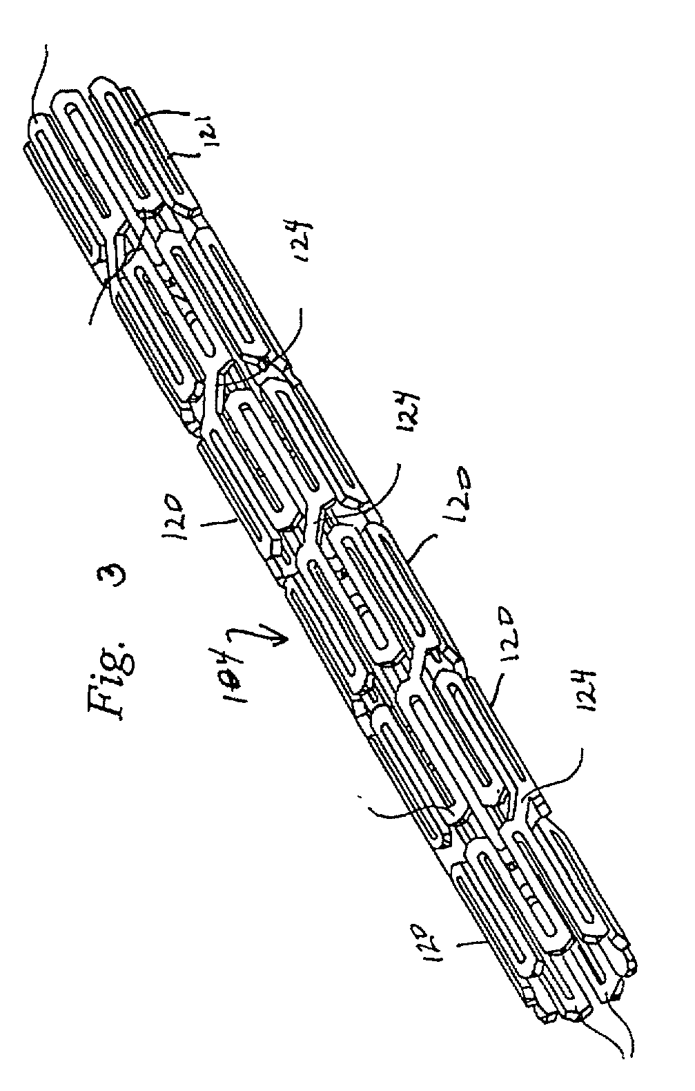
[0026] FIG. 3 shows a perspective view of a stent.

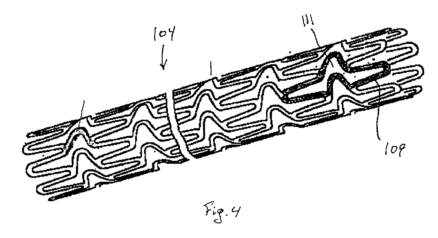
[0027] FIG. 4 shows a perspective view of a stent.

[0028] FIG. 5 shows a stent with a membrane.

[0029] FIG. 6 shows a stent having a plurality of supports and a liner.

[0030] FIG. 7 shows a first stent and a second stent with hooks.

[0031] FIG. 8 shows a second stent extending from the end of a first stent.

[0032] While this invention may be embodied in many different forms, there are described in detail herein specific preferred embodiments of the invention. This description is an exemplification of the principles of the invention and is not intended to limit the invention to the particular embodiments illustrated.

[0033] For the purposes of this disclosure, unless otherwise indicated, like refer...


PUM


Abstract

A second stent having a wall thickness of 0.002 inches or less or a second stent having a tubular surface with openings therethrough where the ratio of the area of the surface to the area of the openings is at least 3:10 may be implanted in a first stent which has been previously implanted in a bodily vessel.

Description

BACKGROUND OF INVENTION[0001] A stenosis of an artery is a constriction or narrowing of the artery. The stenosis may be as a result of the buildup up of cholesterol, fat or other substances. Regardless of the cause of the stenosis, a stenosis can be life threatening. Stenoses of coronary arteries, for example, can diminish the flow of blood to the heart leading to heart damage and, possibly, death.[0002] A number of methods have been developed for widening arteries which have become stenosed. These methods include stenting, percutaneous transluminal coronary angioplasty (PTCA), coronary artery bypass graft (CABG) procedures and the use of drugs and / or radiation.[0003] Of the various methods of widening arteries which have become stenosed, stenting has proven to be of particular value in lowering the rate of restenosis or formation of new stenoses following the procedure. Even stented regions of a vessel, however, can restenose.[0004] Restenosis only occurs in a fraction of stented p...

Claims


Application Information

Patent Timeline
IPC IPC(8): A61F2/00A61F2/82A61F2/86
CPCA61F2/07A61F2/852A61F2/86A61F2/91A61F2220/005A61F2250/0063A61F2250/0067A61F2210/0076A61F2220/0033A61F2002/826
Inventor SIMSO, ERIC J.MILLER, MATTHEW J.
Owner BOSTON SCI SCIMED INC
Why Eureka
Try Eureka