Wastewater treatment process

a technology of wastewater treatment and wastewater, applied in water/sludge/sewage treatment, biological water/sewage treatment, chemical instruments and processes, etc., can solve the problems of sludge settling, nutrient removal is difficult, and additional steps are required, so as to improve the efficiency of the nutrient removal process of activated sludg

Inactive Publication Date: 2001-11-29
KIM SUNGTAI +2
View PDF0 Cites 49 Cited by
  • Summary
  • Abstract
  • Description
  • Claims
  • Application Information

AI Technical Summary

Benefits of technology

The technical effect of this patent is to make more efficient the process of removing nitrogen from wastewater by using activated sludge.

Problems solved by technology

The technical problem addressed in this patent text needs to be identified by a senior R&D personnel who has read it through.

Method used


Image

  • Wastewater treatment process
  • Wastewater treatment process
  • Wastewater treatment process

Examples


Embodiment Construction

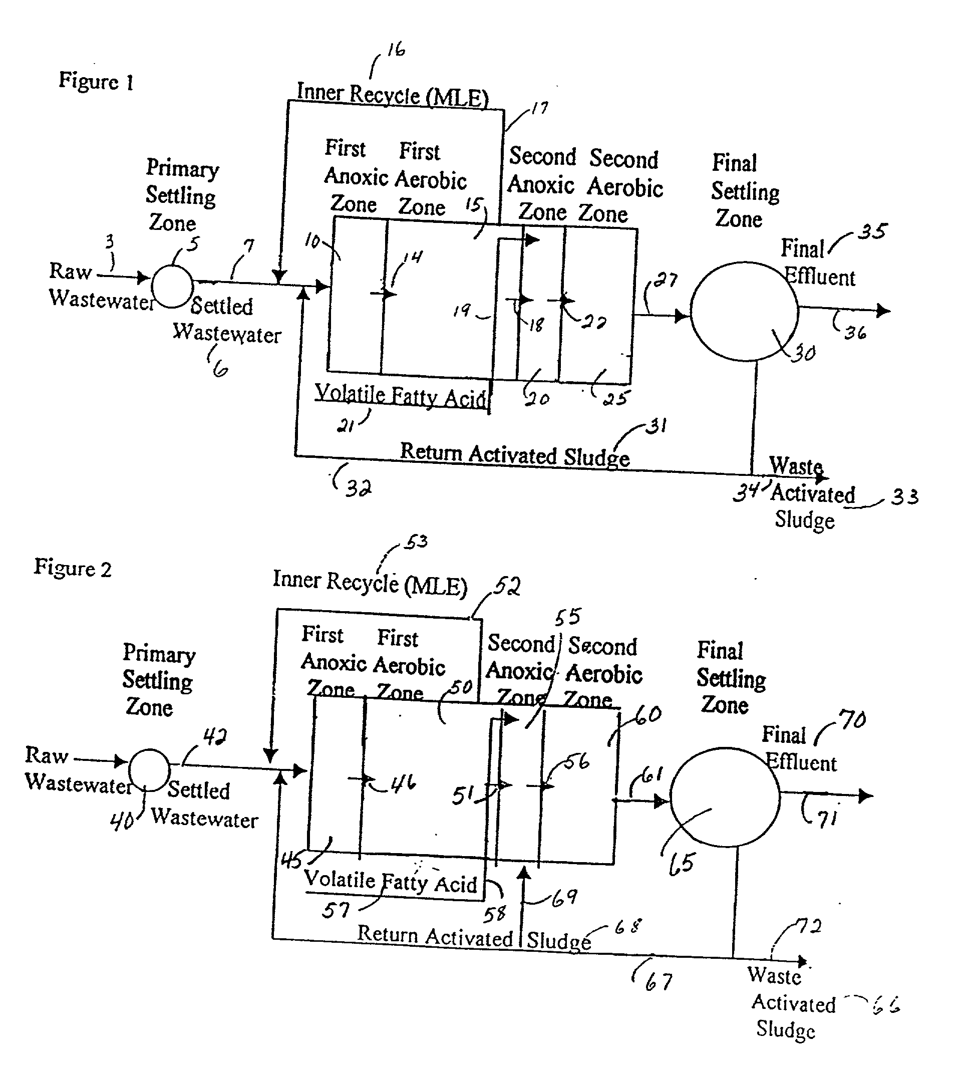
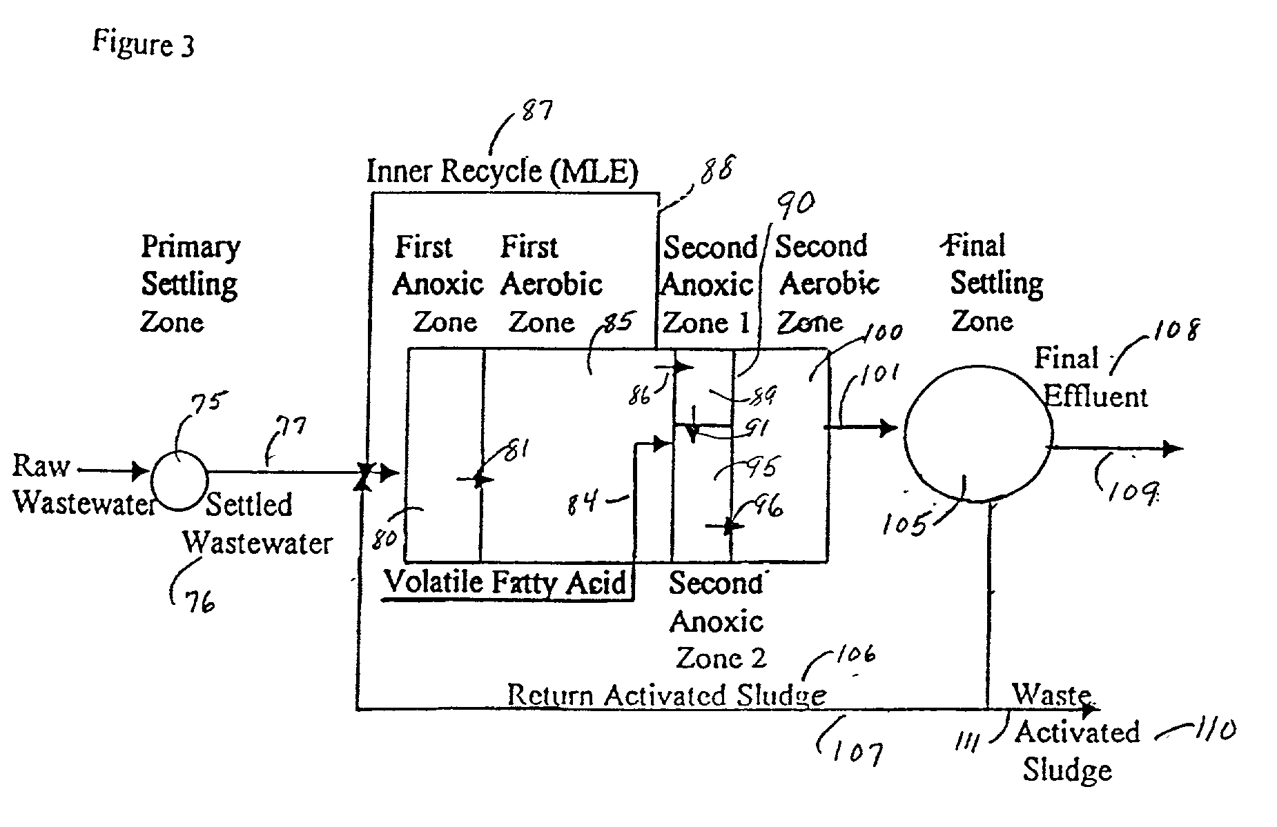
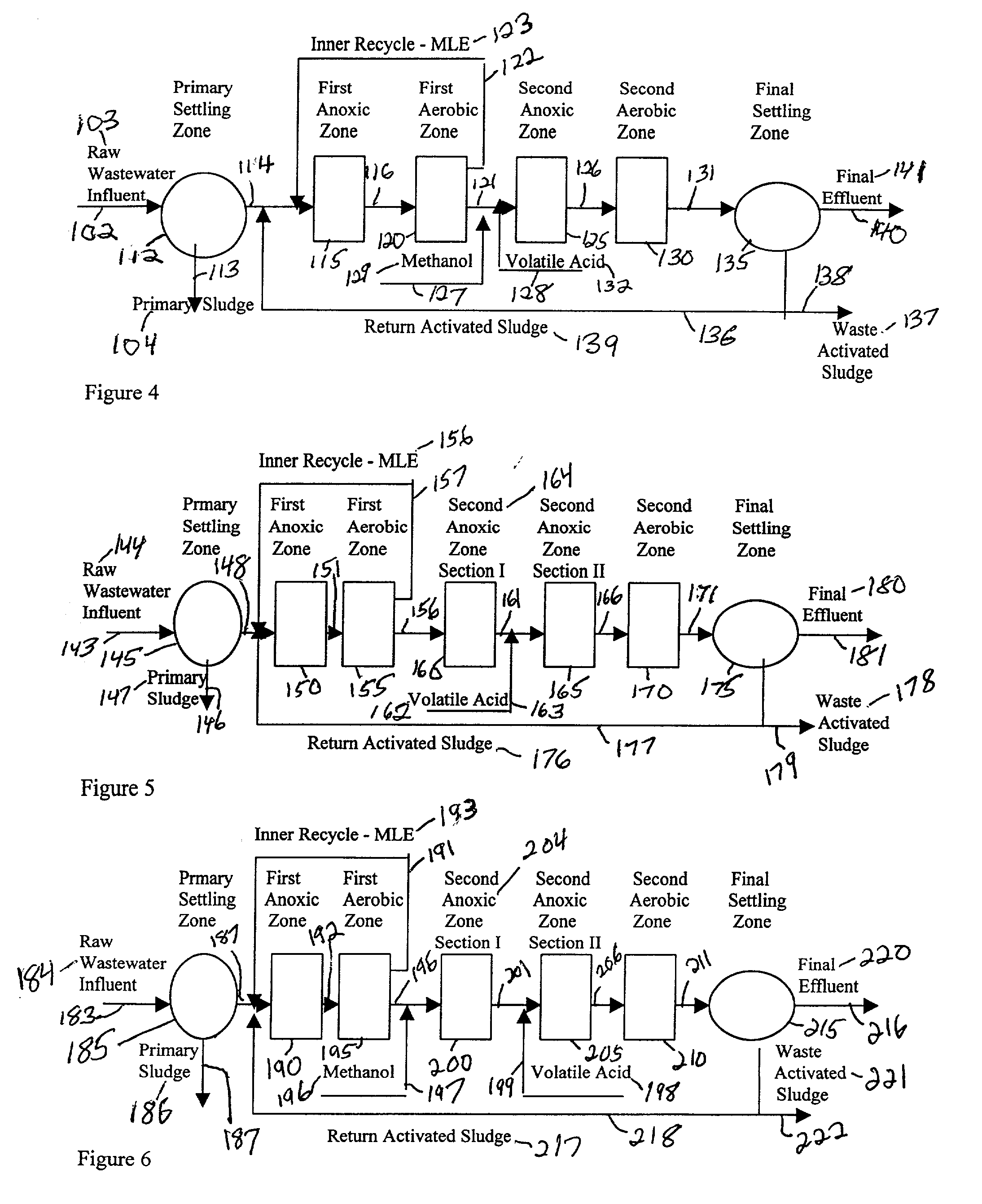
[0086] An embodiment of the process of FIG. 1 according to the invention will be termed PENReP (including activated sludge MLE-type inner recycle). The process was tested in the field with primary settled wastewater from the Rockland County, NY, (Sewer District No. 1) wastewater treatment plant in Orangeburg, N.Y., USA. The test data covered the period from Sept. 15, 1999 to Jan. 11, 2000. The operating conditions for the test period are shown in TABLE 1 and the test results are shown in TABLE 2.

1TABLE 1 Acetic acid Run No. Flow (Gpm) HRT (hours) SRT (days) (mg / l) Qr / Q 1 2.5 8 10 50 1 2 4 5 5 50 1 3 4 5 5 50 0.5

[0087]

2TABLE 2 Total InorganicAbsorbance Nitrogen, o-PO.sub.4 SS Soluble (355 nm) Process Stream mg / l as P, mg / l mg / l COD mg / l units Run 1 Settled Primary 32.64 2.98 75 113 --Effluent PENReP 1.15 0.05 5.2 20 0.049 Effluent Run 2 Settled Primary 41.98 3.21 69 96 --Effluent PENReP 1.5 0.11 2.5 18 0.041 Run 3 Settled Primary 45.11 3.3 74 130 --Effluent PENReP 1.52 0.08 3 19 0.04...


PUM


Abstract

A wastewater treatment process providing nitrogen, phosphorus, biochemical oxygen demand (BOD) and suspended solids removal comprises the steps of: passing wastewater containing ammonia nitrogen, phosphate, BOD and suspended solids, said wastewater mixed with recycled activated sludge from a subsequent step, into a first anoxic zone therein reducing nitrate nitrogen from the recycled sludge to molecular nitrogen; passing effluent from the first anoxic zone to a first aerobic zone therein oxidizing at least a portion of the BOD and oxidizing at least a portion of the ammonia nitrogen to nitrate nitrogen; recycling a portion of the contents at the end of the first aerobic zone back to the first anoxic zone; passing the effluent of the first aerobic zone to a second anoxic zone; introducing volatile fatty acid such as acetic acid into the second anoxic zone therein releasing phosphorus into a liquid phase; passing effluent from the second anoxic zone including the volatile fatty acid to a second aerobic zone therein substantially absorbing phosphorus into biomass and removing and/or oxidizing ammonia nitrogen; passing effluent from the second anoxic zone to a final settling zone therein separating: (i) a purified wastewater having decreased nitrogen, phosphorus, BOD and suspended solids and (ii) a sludge containing suspended solids, phosphate and BOD; and recycling at least a portion of the sludge (ii) to the first anoxic zone. In another embodiment, at least a portion of the sludge (ii) is also recycled to the second anoxic zone. In yet another embodiment, the second anoxic zone is divided into a first section and a second section. In the first section, anoxic conditions are established and in the second section, volatile fatty acid is added after anoxic conditions have been established.

Description


Claims


Application Information

Patent Timeline
Owner KIM SUNGTAI
Why Eureka
Try Eureka