Polarized light irradiation apparatus

a technology of polarized light and irradiation apparatus, which is applied in the direction of polarising elements, instruments, printing, etc., can solve the problems of reducing the ratio and unable to achieve the desired extinction ratio

Inactive Publication Date: 2001-12-13
USHIO DENKI KK
View PDF2 Cites 11 Cited by
  • Summary
  • Abstract
  • Description
  • Claims
  • Application Information

AI Technical Summary

Problems solved by technology

However, in the apparatus in FIG. 11, even if a nearly linearly polarized light (with a good extinction ratio, between 20:1 and 15:1, for example) is emitted from the polarization element, it sometimes happens that when the polarization element is rotated to change the direction of polarization of the polarized light irradiating the substrate, the extinction ratio drops (to 6:1, for example) and the desired extinction ratio cannot be obtained.

Method used


Image

  • Polarized light irradiation apparatus
  • Polarized light irradiation apparatus
  • Polarized light irradiation apparatus

Examples


first embodiment

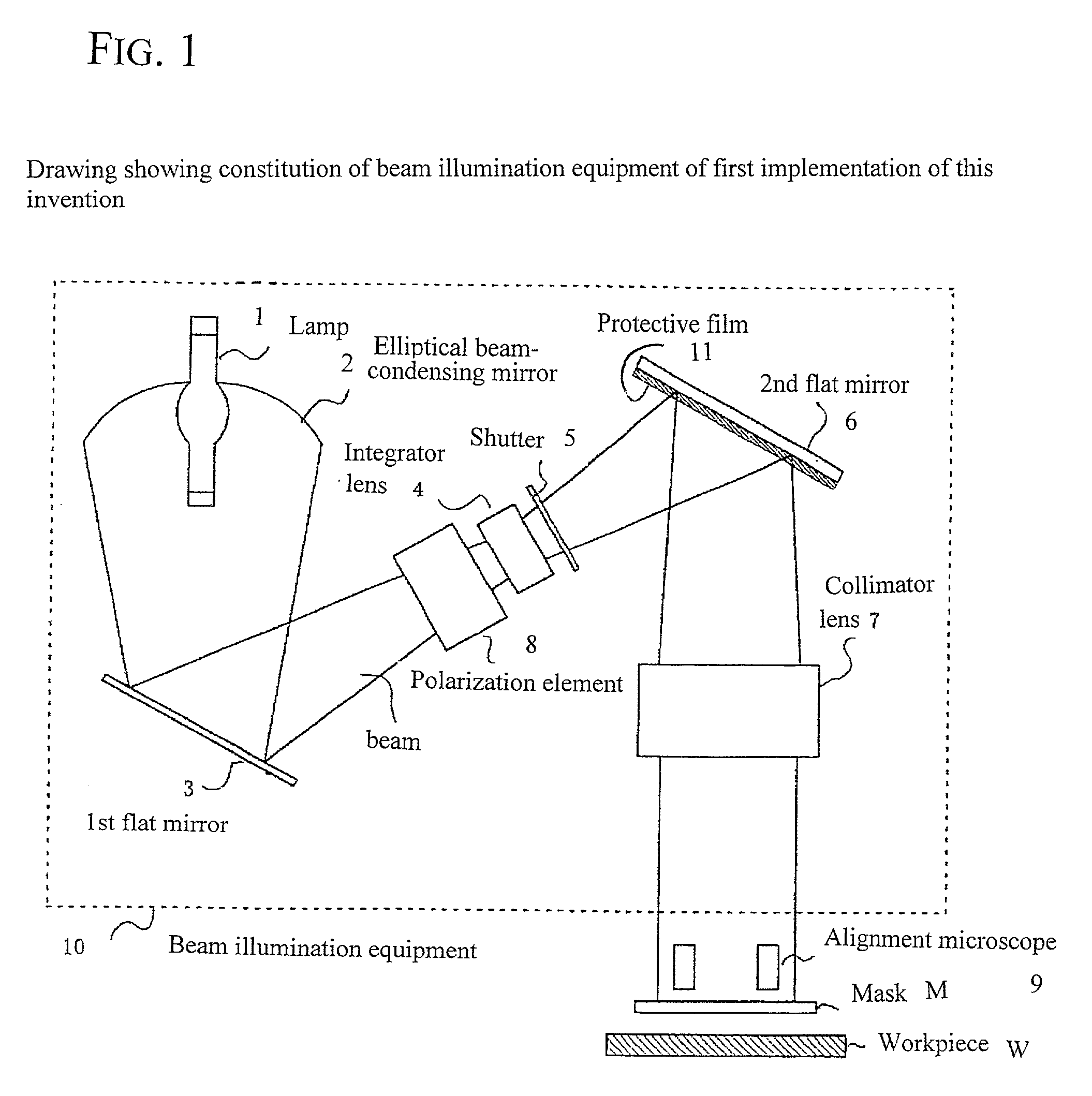
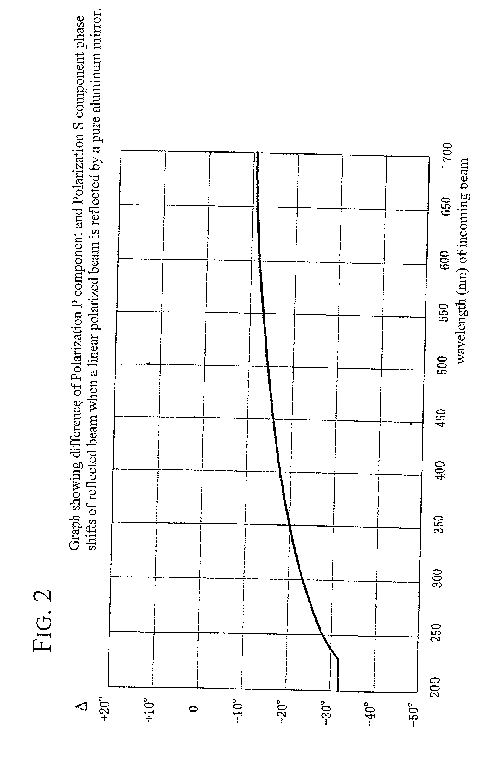
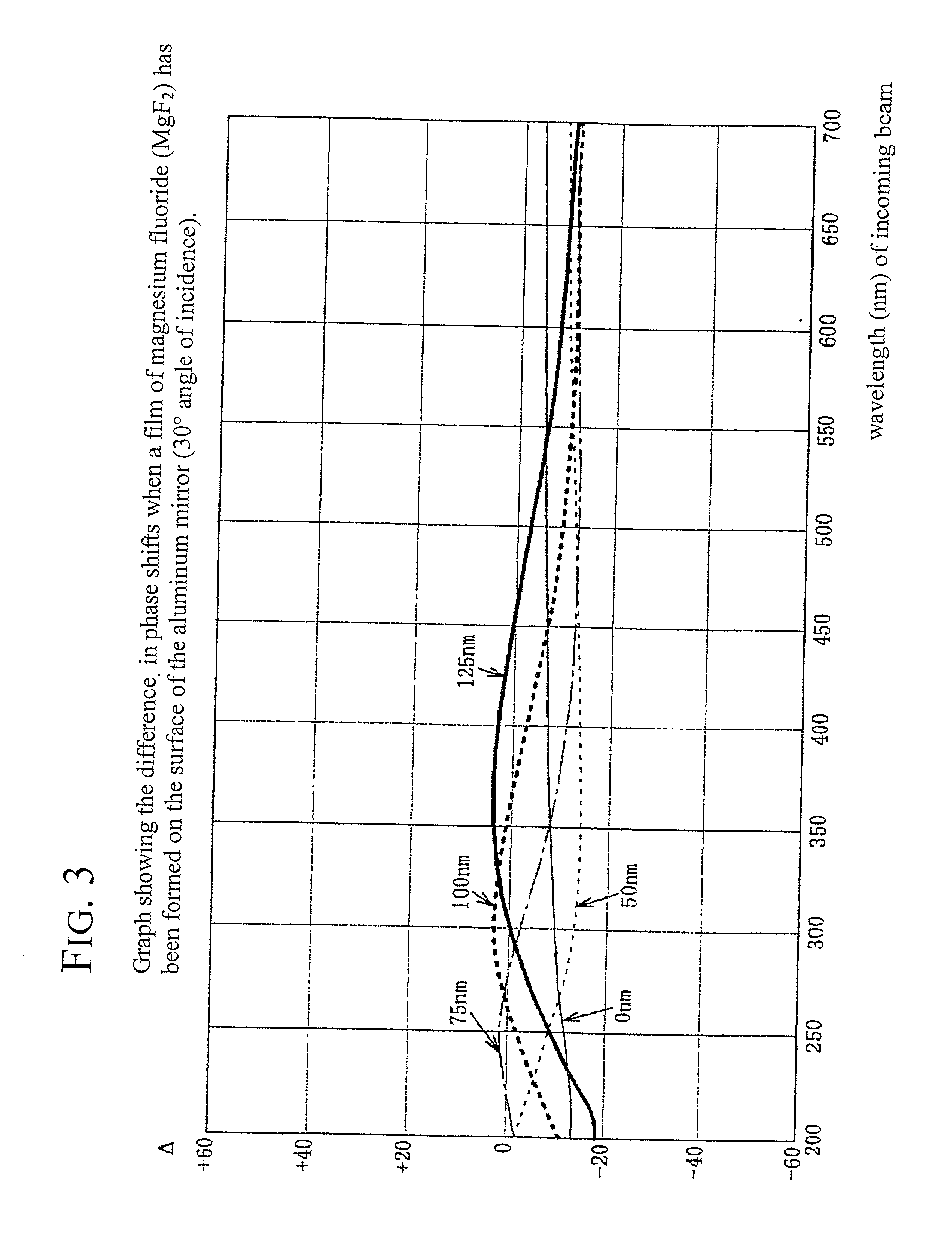
[0052] the polarized light irradiation apparatus of the invention is shown in FIG. 1. In FIG. 1, the element identified are the same as those in FIG. 11, but in this embodiment, the surface of the second plane mirror 6 has been treated with a dielectric layer (protection layer) 11. The material of the dielectric layer and its thickness are selected, in connection with the angle of incidence of the polarized light on the second plane mirror 6 and the wavelength needed to align the optical alignment layer formed on the workpiece W, so that the difference in phase shifts .DELTA. of the polarization P component and polarization S component of the polarized light that reflects is no greater than 20.degree.. The second plane mirror 6 is, for example, an aluminum mirror, and the dielectric layer 11 formed on its surface (hereafter protection layer 11) can be, for example, a magnesium fluoride (MgF.sub.2) layer or a silicon dioxide (SiO.sub.2) layer.

[0053] In FIG. 1, the light from the lamp...

second embodiment

[0079] FIG. 7 illustrates a polarized light irradiation apparatus of this invention. Components in FIG. 7 are labeled with the same key as shown in FIG. 1. In this embodiment, the second plane mirror 6 is replaced with two plane mirrors 6a, 6b (called the second and third plane mirrors). The angles of incidence of the polarized light to the plane mirrors 6a, 6b are selected appropriately to minimize the difference .DELTA. between phase shifts of the polarization P component and the polarization S component of the reflected light from the plane mirror 6b that irradiates the optical alignment layer.

[0080] In FIG. 7, as in FIG. 1, the light from the lamp 1 is condensed by an ellipsoidal condenser mirror 2; the optical path is folded by the first plane mirror 3 and is incident on the polarization element 8. The polarization element 8 is a device with multiple glass plates inclined at Brewster's angle with respect to the optical axis. The light of polarization P passes through but most l...

third embodiment

[0088] FIGS. 10a, 10b, and 10c illustrate the invention. These figures show only the second plane mirror of the polarized light irradiation apparatus shown in FIG. 1; the rest of elements are omitted. FIG. 10a is an oblique view, while FIG. 10b is a view from direction of arrow .DELTA. of FIG. 10a, and FIG. 10c is a view from direction B of FIG. 10a.

[0089] In this embodiment, the second plane mirror 6 in FIG. 1 is replaced by two plane mirrors 6a, 6b (second plane mirror 6a and third plane mirror 6b), with the polarized light reflected such that the phase shift is canceled out by the two plane mirrors 6a, 6b. In FIG. 10a, the second plane mirror 6a and the third plane mirror 6b are mirrors made of the same material. They are positioned so that the plane determined by the axis of the incoming polarized light and the axis of the reflected light of the third plane mirror 6b is perpendicular to the plane determined by the axis of the incoming light and the axis of the reflected light of...


PUM


Abstract

A polarized light irradiation apparatus, having at least two plane mirrors, is constructed to prevent reduction of the extinction ratio of the polarized light that irradiates a substrate when there is a change of the direction of polarization of the polarized light that is incident on a reflecting mirror. This is accomplished by forming a protection layer on the surface of the second plane mirror, and selecting the material and optical thickness of the layer in accordance with the angle of incidence and wavelength of the polarized light so that the difference DELTA of the phase shifts of the polarization P component and the polarization S component emerging from the second plane mirror satisfies the condition that DELTA<=±20°. By doing this, there will be no reduction of the extinction ratio of the polarized light that irradiates the substrate W if there is a change in the polarization direction of the polarized light that is incident on the second plane mirror.

Description

[0001] 1. Field of the Invention[0002] This invention relates to polarized light irradiation apparatus for optical alignment of liquid crystals in which an alignment layer of a liquid crystal display element is irradiated with polarized light.[0003] 2. Description of Related Art[0004] Liquid crystal display elements are produced by carrying out an alignment process to align the liquid crystals in the desired direction on an alignment layer formed on the surface of a transparent substrate; two of these transparent substrates are put together with the alignment layers facing inwardly, such that alignment layers are separated by a gap of a desired size, and thereafter, liquid crystal is injected into the gap.[0005] The alignment process for the alignment layer is a technology called optical alignment, in which the alignment layer is exposed by irradiation with polarized light of a particular wavelength.[0006] The most widely used liquid crystal display elements, called TN liquid crysta...

Claims


Application Information

Patent Timeline
IPC IPC(8): G02B27/28G02B5/30G02F1/13G02F1/1337
CPCG02B27/28G02F1/133788G02F1/1337
Inventor GOTO, MANABUSHINBORI, MASASHI
Owner USHIO DENKI KK
Why Eureka
Try Eureka