Very low temperature refrigeration system with controlled cool down and warm up rates and long term heating capabilities
a refrigeration system and very low temperature technology, applied in the direction of defrosting, domestic cooling apparatus, application, etc., can solve the problem of never being able to bypass the defrosting return
- Summary
- Abstract
- Description
- Claims
- Application Information
AI Technical Summary
Benefits of technology
Problems solved by technology
Method used
Image
Examples
sixth embodiment
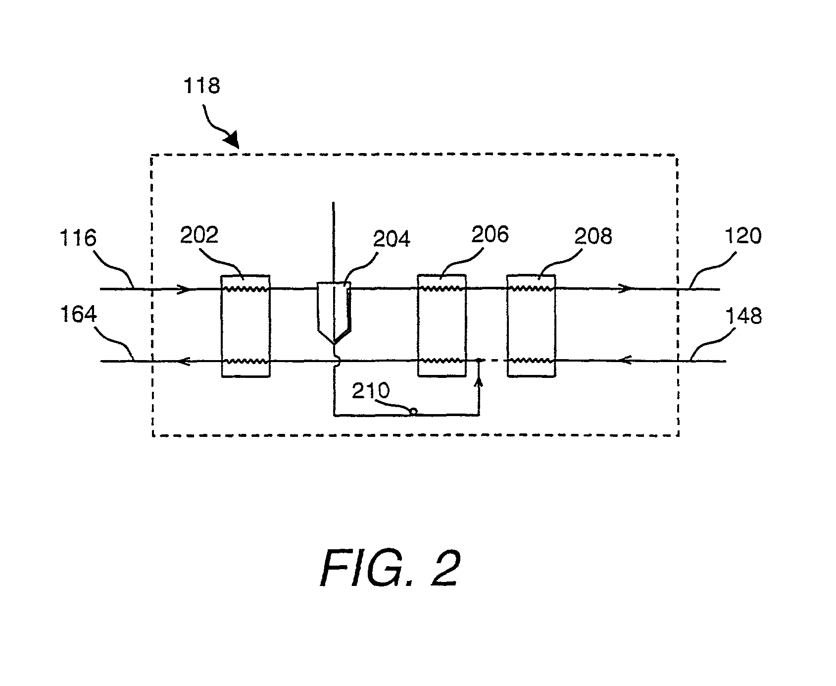
[0093] FIG. 3 illustrates a sixth embodiment in accordance with the invention of the defrost return bypass loop of refrigeration system 300. In this embodiment, an array of return valves are present such that the defrost refrigerant flow is returned to one of several potential places in refrigeration process 118.
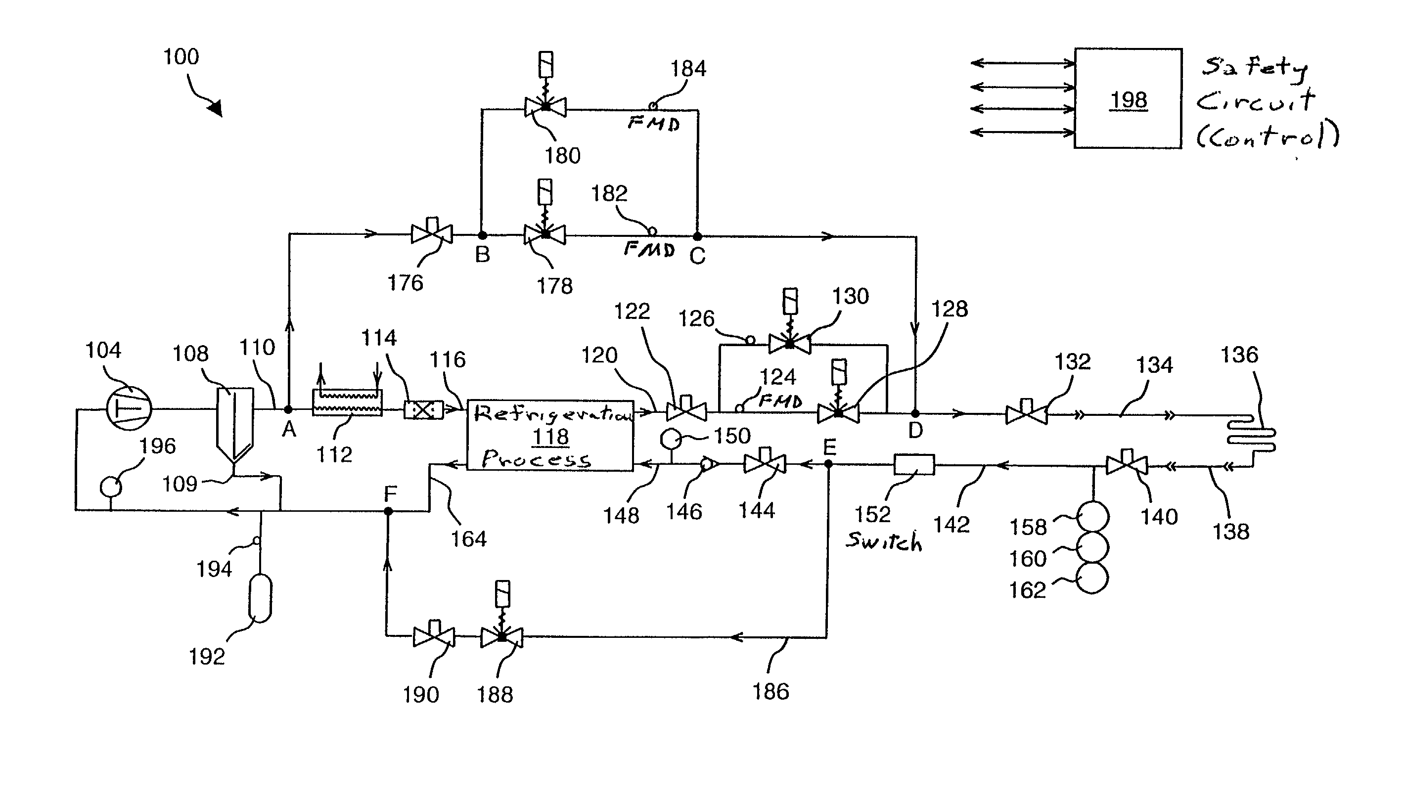
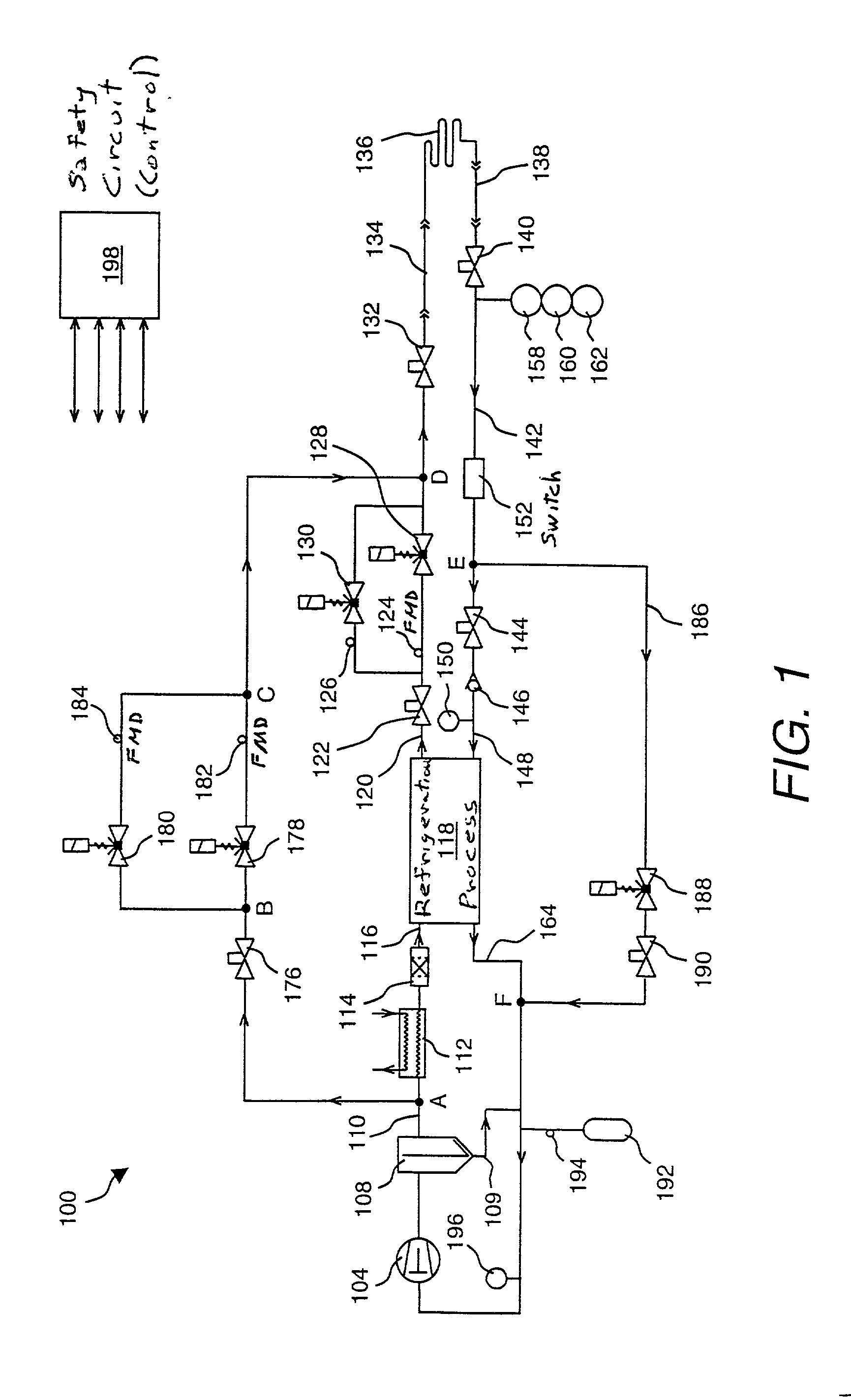
[0094] As an example, refrigeration system 300 of FIG. 3 includes a bypass valve 302, a bypass valve 304, and a bypass valve 306, the inlets of which are hydraulically connected to bypass line 186 connecting to node E along with bypass valve 188. The outlets of bypass valves 302, 304, and 306 are connected back into different points within refrigeration process 118 based on the return refrigerant temperature. Although they are not shown in FIG. 3, service valves may be inserted in line with bypass valves 302, 304, and 306. Those portions of the system not shown in FIG. 3 are similar to FIG. 1.
[0095] This arrangement of bypass valves 302, 304, and 306 allows return gas to be ...
seventh embodiment
[0101] FIG. 5 (eighth embodiment) illustrates another variation of the defrost supply loop of refrigeration system 100. In this embodiment, refrigeration system 500 of FIG. 5 includes a bypass valve 502 arranged in parallel with heat exchanger 402 of the Bypass valve 502 is typically a proportional valve.
[0102] Differing from the seventh embodiment where heat exchanger 402 has no controls to warm the gas, bypass valve 502 provides a method of regulating the amount of heat exchanged with the discharge gas of compressor 104 to achieve a desired refrigerant temperature. The refrigerant is allowed to bypass heat exchanger 402 via bypass valve 502 with controlled flow, thereby allowing the refrigerant temperature to be regulated. Alternatively, bypass valve 502 could be a "chopper" valve that pulses on or off for different lengths of time.
ninth embodiment
[0103] FIG. 6 illustrates another variation 600 (ninth embodiment) of refrigeration system 100, in which a variable shunt valve 602 is inserted between discharge line 110 of compressor 104 and compressor suction line 164.
[0104] In this embodiment, the compressor suction temperature is regulated as a way to control the discharge temperature. Variable shunt valve 602 allows discharge flow to be diverted directly back into compressor suction line 164 feeding compressor 104. A temperature sensor (not shown) from FMD 182 or FMD 184 in the defrost supply loop provide feedback to variable shunt valve 602 to control its flow rate.
[0105] When this embodiment is used in combination with embodiment 7 or 8, then the temperature to be controlled may be the discharge temperature itself, because heat exchanger 402 of embodiment 7 and 8 is exchanging heat with the discharge gas having a typical temperature between +80 and +130.degree. C. Thus the refrigerant temperature exiting the defrost supply l...
PUM
 Abstract
Description
Claims
Application Information
 - R&D
- Intellectual Property
- Life Sciences
- Materials
- Tech Scout
- Unparalleled Data Quality
- Higher Quality Content
- 60% Fewer Hallucinations
Browse by: Latest US Patents, China's latest patents, Technical Efficacy Thesaurus, Application Domain, Technology Topic, Popular Technical Reports.
© 2025 PatSnap. All rights reserved.Legal|Privacy policy|Modern Slavery Act Transparency Statement|Sitemap|About US| Contact US: help@patsnap.com


