Induction foil cap sealer

a sealing head and foil technology, applied in the field of induction sealing apparatus, can solve the problems of high cost, bulky and inefficient water cooling system, and increased temperature of the coil and any surrounding structure, and achieve the effect of reducing the cost of sealing head cooling

Inactive Publication Date: 2002-02-21
AUTO KAPS
View PDF0 Cites 39 Cited by
  • Summary
  • Abstract
  • Description
  • Claims
  • Application Information

AI Technical Summary

Problems solved by technology

In conventional systems, high currents are produced in the coil of the sealing head and, due to the relatively high resistance of the coil, results in a drastic elevation of the temperat

Method used


Image

  • Induction foil cap sealer
  • Induction foil cap sealer
  • Induction foil cap sealer

Examples


Embodiment Construction

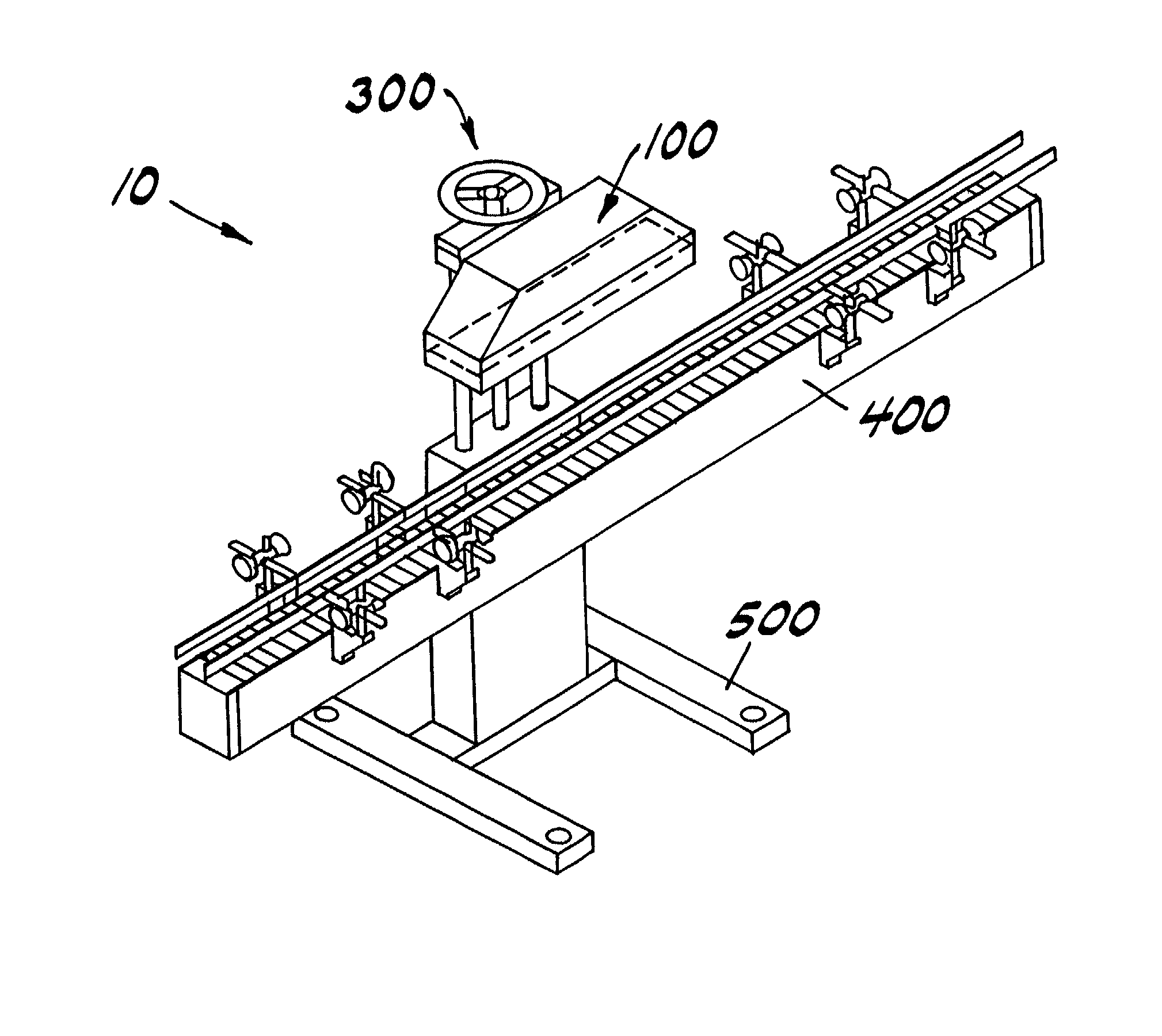
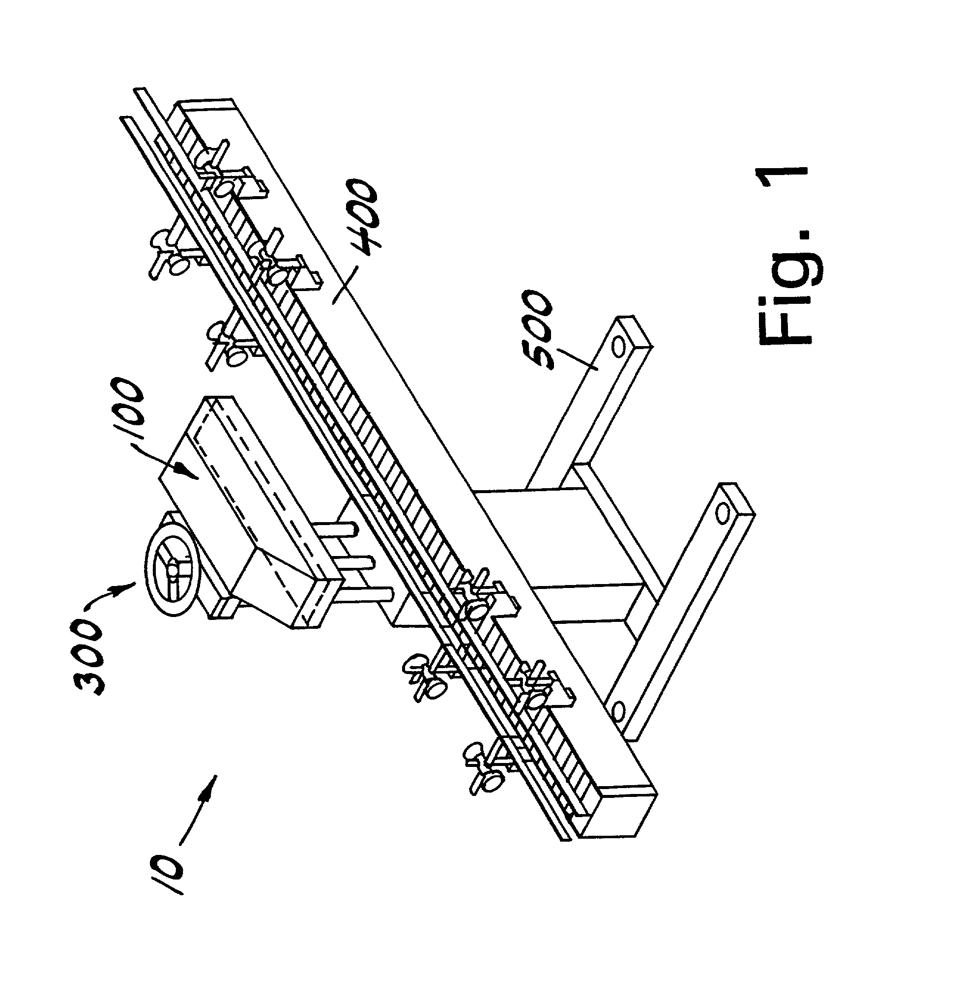
[0038] Referring now to the drawings wherein like numerals indicate like elements, there is shown in FIG. 1 an induction sealing conveyor system 10. The induction sealing conveyor system 10 includes an induction sealing unit 100, an adjustment mechanism 300, a conveyor 400, and a base 500. The adjustment mechanism 300 adjustably couples the induction sealing unit 100 to the base 500. Thus, the induction sealing unit 100 may be raised or lowered with respect to the base 500 and the conveyor 400 for insuring that the induction sealing unit is the proper distance from a container (not shown) to be sealed which travels down the conveyor 400. The adjustment mechanism 300 and the conveyor 400 are well-known in the art and any of the known adjustment mechanisms and conveyors can be used with the induction sealing unit 100 of the present invention.

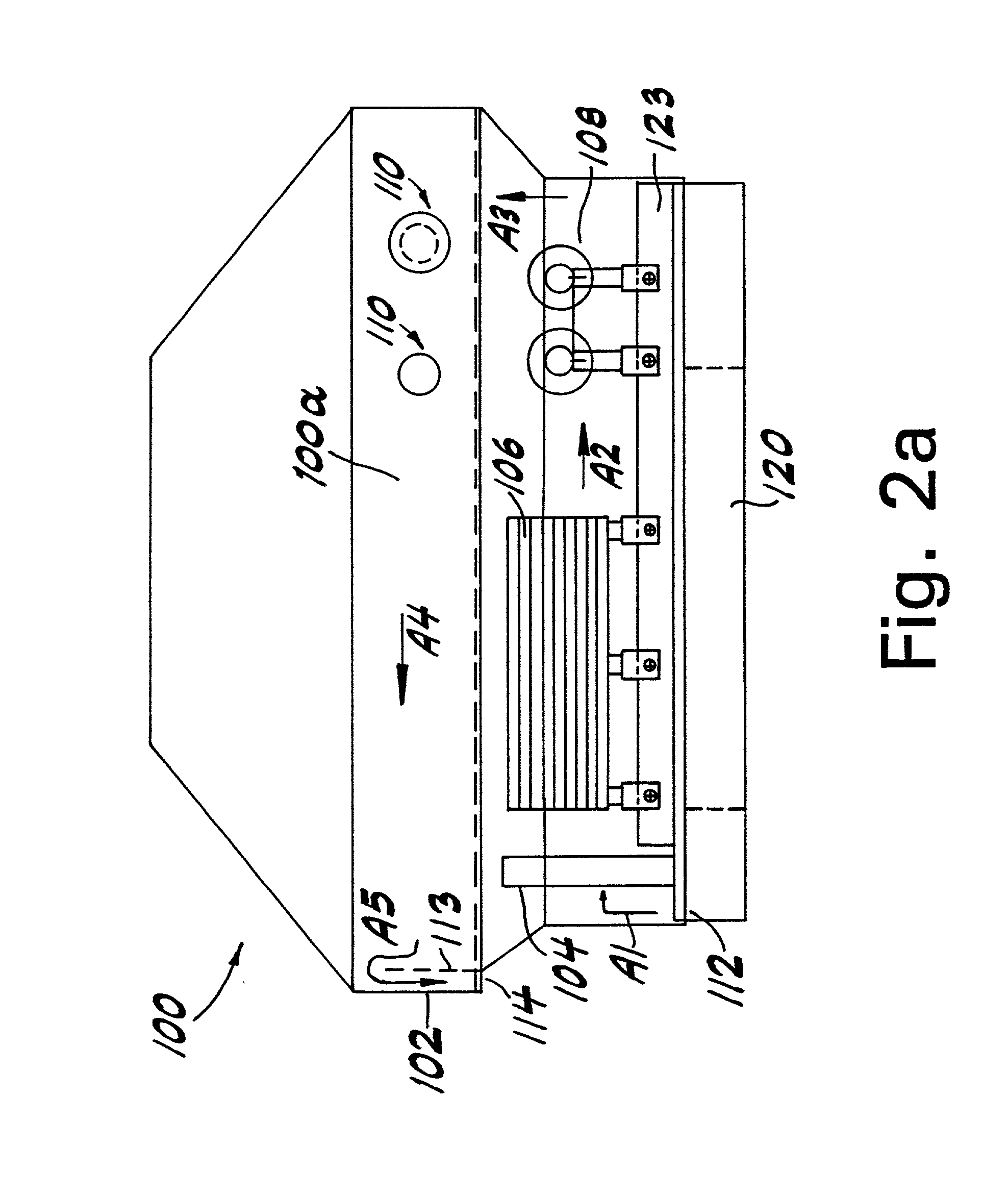
[0039] With reference to FIG. 2a, the induction sealing unit comprises a housing 102 and start and stop switches 110 disposed on the housing 102 ...


PUM

PropertyMeasurementUnit
Electrical conductivityaaaaaaaaaa
Lengthaaaaaaaaaa
Electrical resistanceaaaaaaaaaa

Abstract

An sealing system includes a frame, a ferrite core disposed within the frame, and a litz wire coil disposed proximate to the ferrite core for producing an electromagnetic field within the ferrite core, where the ferrite core and litz wire coil are adapted to direct the electromagnetic field toward a foil to seal an opening of a container with the foil. The sealing head is air cooled within the induction sealing unit.

Description

[0001] This application is based on and claims priority to:[0002] (1) U.S. patent application No. Ser. 09 / 138,159, filed Aug. 21, 1998, entitled INDUCTION FOIL CAP SEALER, which is based on and claims priority to U.S. patent application Ser. No. 08 / 966,305, filed Nov. 7, 1997, entitled INDUCTION FOIL CAP SEALER, now abandoned, which is based on and claims priority to U.S. Provisional Application No. 60 / 031,048, filed Nov. 15, 1996, entitled INDUCTION FOIL CAP SEALER, and U.S. Provisional Application No. 60 / 030,488, filed Nov. 15, 1996, entitled INDUCTION FOIL CAP SEALER; and[0003] (2) U.S. patent application No. Ser. 08 / 964,572, filed Nov. 5, 1997, entitled SLOTTED INDUCTION SEALER, which is based on and claims priority to U.S. Provisional Application No. 60 / 058,312, filed Sep. 9, 1997, entitled INDUCTION FOIL CAP SEALER, U.S. Provisional Application No. 60 / 031,048, filed Nov. 15, 1996, entitled INDUCTION FOIL CAP SEALER, and U.S. Provisional Application No. 60 / 030,488, filed Nov. 1...

Claims


Application Information

Patent Timeline
IPC IPC(8): B29C65/02B65B7/16B65B7/28B65B51/22B65B57/04B65G43/08H05B6/02H05B6/14
CPCB29C65/3656B29C66/836B29C66/72321B29L2031/7158B65B7/168B65B7/2878B65B51/227B65B57/04B65G43/08B29C65/3644B29C65/3668Y10S53/02B29C66/542B29C66/545B29C66/53421B29C65/368B29C66/81811B29C66/81871B29C66/8122B29C66/112B29C66/114B29K2827/18
Inventor SARLES, FREDERICK W.JOHNSON, DOUGLAS A.
Owner AUTO KAPS
Why Eureka
Try Eureka