X-ray tube with high speed beam steering electromagnets

a technology of x-ray tubes and electromagnets, applied in the field of x-ray tubes, can solve the problems of increasing transition time, slow response time, and reducing exposure at the required power level

Active Publication Date: 2012-07-12
GENERAL ELECTRIC CO
View PDF2 Cites 12 Cited by
  • Summary
  • Abstract
  • Description
  • Claims
  • Application Information

AI Technical Summary

Problems solved by technology

Such induction may slow response time for deflection of the electron stream, and thus may result in increased transition time and reduced exposure at a required power level.

Method used


Image

  • X-ray tube with high speed beam steering electromagnets
  • X-ray tube with high speed beam steering electromagnets
  • X-ray tube with high speed beam steering electromagnets

Examples


Embodiment Construction

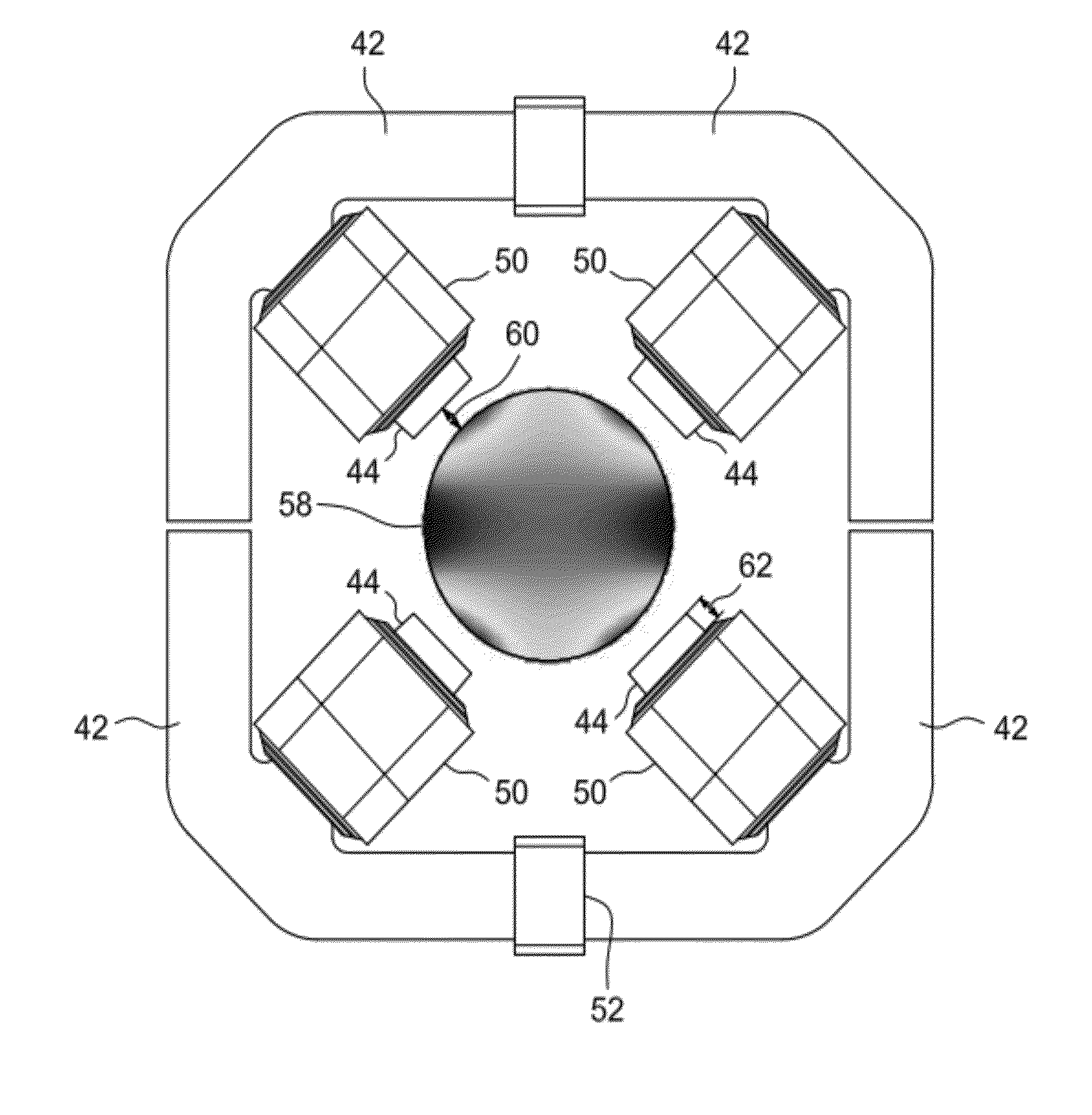
[0013]The present embodiments are directed towards a system and method for enhancing response time of a steering magnet assembly. For example, in embodiments of an X-ray tube wherein the steering magnet assembly controls steering and wobble of an electron stream through the use of electromagnets, eddy currents induced into the beam pipe, magnet core, and magnet windings may be reduced by selecting an appropriate core material, selecting an appropriate material for the electromagnet coil windings, and defining proper positioning of the magnet poles with respect to the electron beam pipe. The reduction in eddy currents may considerably reduce the response time of the steering magnet assembly.

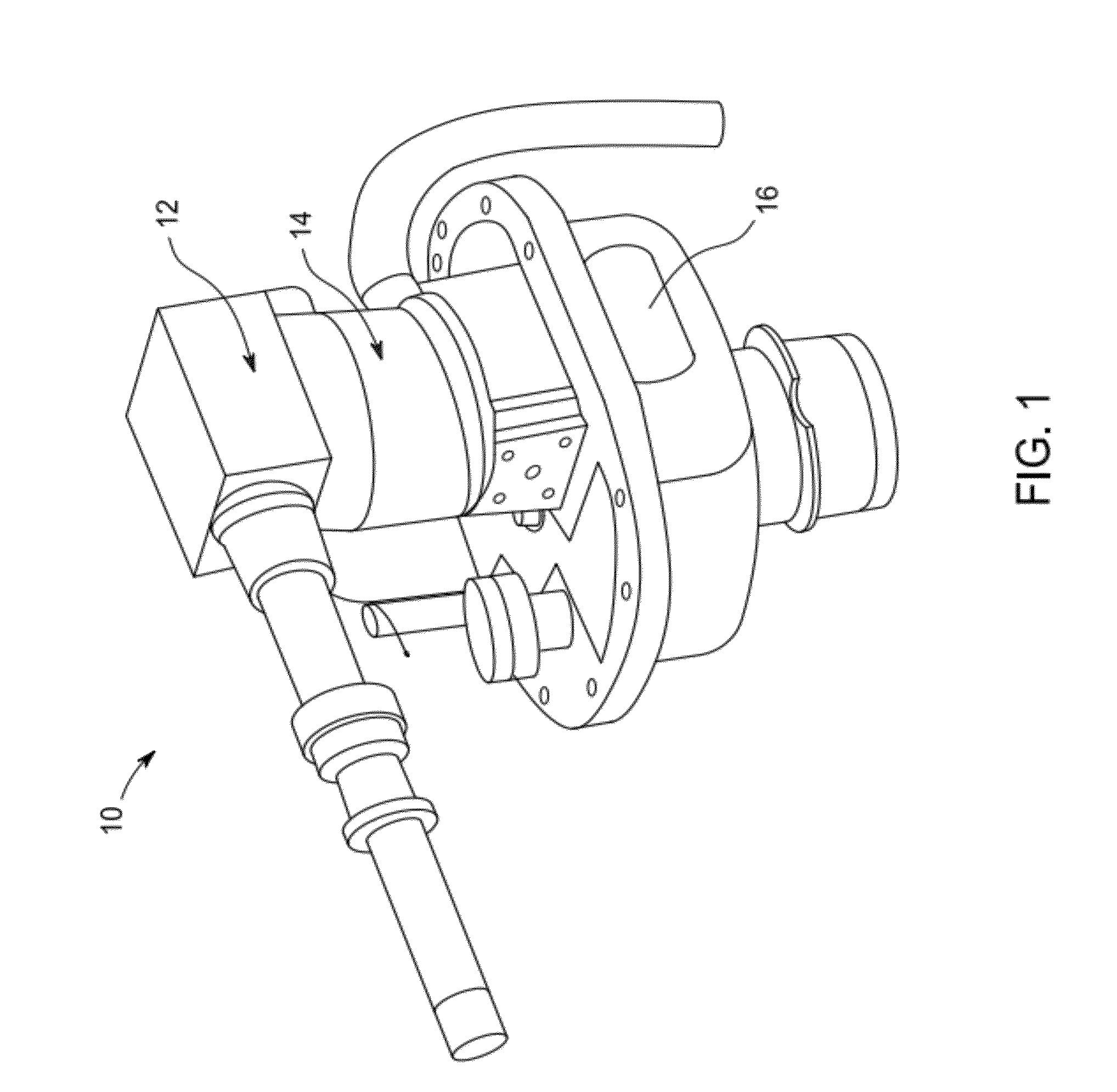
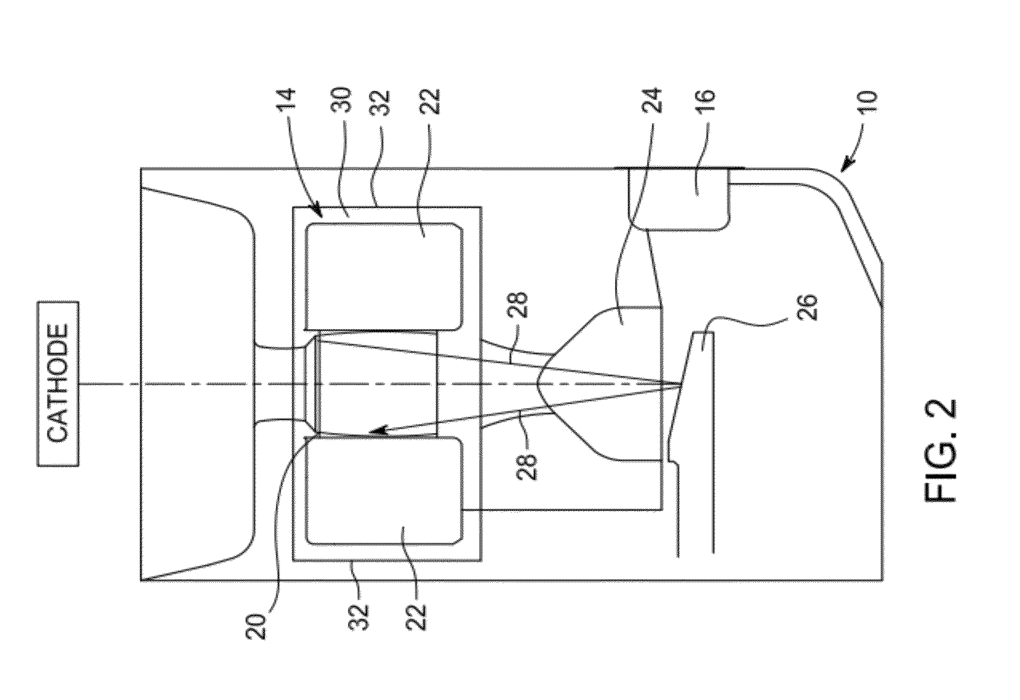
[0014]The electromagnet steering techniques described herein may be utilized in an X-ray tube, such as X-ray tubes utilized in digital and photographic projection X-ray systems, fluoroscopy imaging systems, tomosynthesis imaging systems, CT imaging systems, and so on. FIG. 1 illustrates such an X-...


PUM

PropertyMeasurementUnit
frequencyaaaaaaaaaa
frequencyaaaaaaaaaa
diameteraaaaaaaaaa

Abstract

The present embodiments relate to efficient electron beam steering within X-ray tubes, for example X-ray tubes used in CT imaging. In one embodiment, and X-ray tube with enhanced electron beam steering is provided. The X-ray tube includes an electron beam source, a target configured to generate X-rays when impacted by an electron beam from the electron beam source, and a steering magnet assembly having a plurality of ferrite cores and a plurality of litz wire coils wound on the ferrite cores.

Description

BACKGROUND OF THE INVENTION[0001]The subject matter disclosed herein relates to X-ray tubes and, in particular, to electron beam steering within an X-ray tube.[0002]In non-invasive imaging systems, X-ray tubes are used in fluoroscopy, projection X-ray, tomosynthesis, and computer tomography (CT) systems as a source of X-ray radiation. Typically, the X-ray tube includes a cathode and a target. A thermionic filament within the cathode emits a stream of electrons towards the target in response to heat resulting from an applied electrical current, with the electrons eventually impacting the target. A steering magnet assembly within the X-ray tube may control the size and location of the electron stream as it hits the target. Once the target is bombarded with the stream of electrons, it produces X-ray radiation.[0003]The X-ray radiation traverses a subject of interest, such as a human patient or baggage, and a portion of the radiation impacts a detector or photographic plate where the im...

Claims


Application Information

Patent Timeline
Patent Type & Authority Applications(United States)
IPC IPC(8): H01J35/30H01F7/06
CPCY10T29/4902H01J35/14H01J35/153
Inventor KOPPISETTY, KALYANWESTCOT, ETHAN JAMESROGERS, CAREY SHAWN
Owner GENERAL ELECTRIC CO
Why Eureka
Try Eureka