Carbon nanotubes litz wire for low loss inductors and resonators

a technology of carbon nanotubes and litz wires, applied in the direction of insulated conductors, cables, conductors, etc., can solve the problems of significant power loss, significant overall power loss, and increased conductor losses due to skin effects

Active Publication Date: 2010-05-04
GOOGLE TECHNOLOGY HOLDINGS LLC
View PDF9 Cites 10 Cited by
  • Summary
  • Abstract
  • Description
  • Claims
  • Application Information

AI Technical Summary

Problems solved by technology

This phenomenon is often referred to as the “skin effect.” In high frequency applications, the skin effect becomes more pronounced, especially in such devices as inductors and transformers, resulting in a substantial power loss.
At high UHF frequencies, conductor losses increase due to the skin effect, even with conventional copper Litz wires.
This is because at UHF frequencies, the skin effect in the individual strands become so pronounced that the overall power loss becomes significant.
However, the required diameter of a copper wire used as a component wire of a Litz wire for UHF applications would be so fine that it would not be able to withstand the stresses imparted on it as a result of conventional manufacturing processes and ordinary use.
Currently, the minimum size of an antenna is limited by the amount of inductance that can be used to match the capacitance exhibited by the antenna.
A similar problem exists when trying to miniaturize amplifiers.
However, no inductor exists that is both small enough to work effectively with a miniature amplifier or antenna and capable of providing sufficient inductance to match the capacitance of the miniature antenna or amplifier.

Method used


Image

  • Carbon nanotubes litz wire for low loss inductors and resonators
  • Carbon nanotubes litz wire for low loss inductors and resonators
  • Carbon nanotubes litz wire for low loss inductors and resonators

Examples


Embodiment Construction

[0032]A preferred embodiment of the invention is now described in detail. Referring to the drawings, like numbers indicate like parts throughout the views. As used in the description herein and throughout the claims, the following terms take the meanings explicitly associated herein, unless the context clearly dictates otherwise: the meaning of “a,”“an,” and “the” includes plural reference, the meaning of “in” includes “in” and “on.”

[0033]Also, as used herein “upper frequency range” includes frequencies in the UHF and SHF ranges. Generally, a frequency above 300 MHz (such as a frequency in the range of from 800 MHz to 10 GHz) would be included in an upper frequency range.

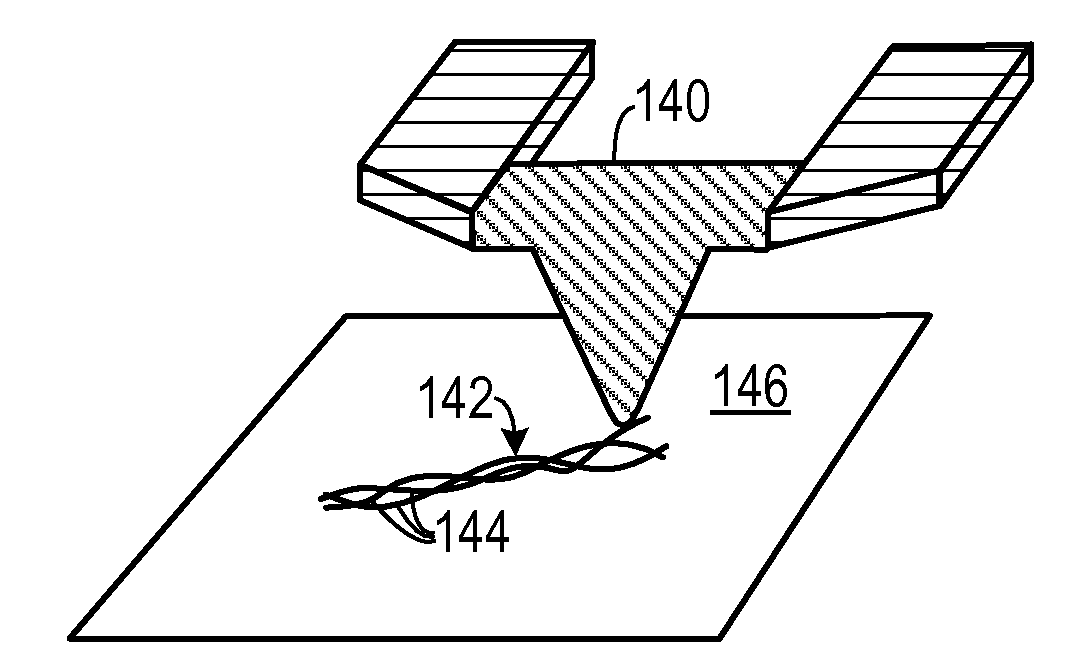
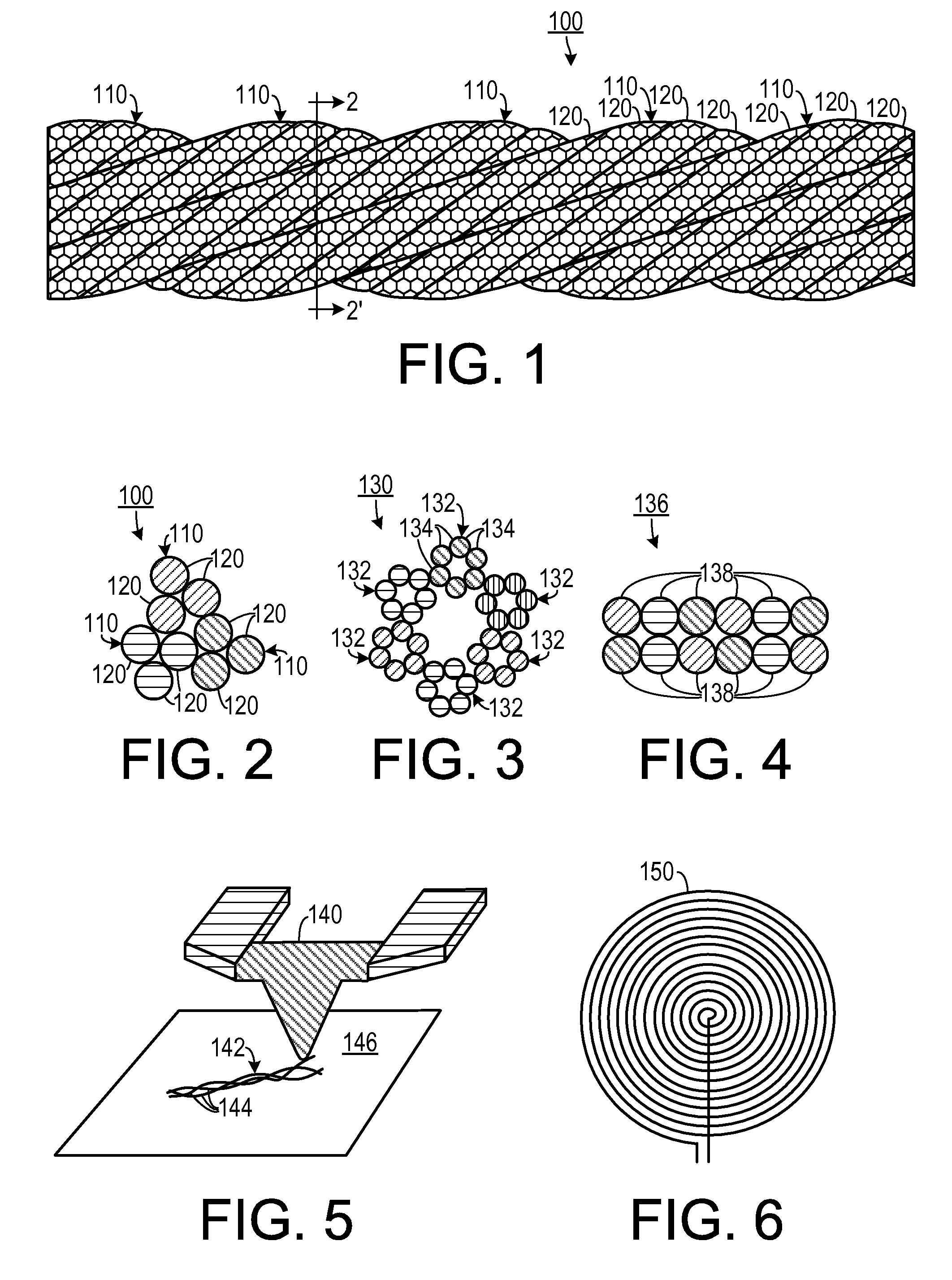
[0034]As shown in FIGS. 1 and 2, one embodiment includes a Litz wire 100 that is woven from a plurality of nano-scale conductors 120. The nano-scale conductors 120 could be nanotubes (such as carbon nanotubes) or could be other types of nano-scale conductors, including nano-ribbons, nano-rods and nano-wires, or a co...


PUM

PropertyMeasurementUnit
frequencyaaaaaaaaaa
frequencyaaaaaaaaaa
frequencyaaaaaaaaaa

Abstract

An upper frequency-range circuit (160) includes a load element (168) exhibiting a capacitive load impedance. A first matching network (166) includes at least one nano-scale Litz wire (100) inductor. The first matching network (166) exhibits an inductive reactance that nominally matches the capacitive load reactance. An electrical conductor for providing connections for radio-frequency signals includes a plurality of nano-scale conductors (120) that are arranged in the form of a Litz wire (100). In one method of making a Litz wire (142), a plurality of carbon nanotubes (144) is placed on a substrate (146). The carbon nanotubes (144) are woven according to a predefined scheme so as to form a Litz wire (142). An inductor may be formed by manipulating the Litz wire (100) to form a coil (150).

Description

BACKGROUND OF THE INVENTION[0001]1. Field of the Invention[0002]The present invention relates to electronic wiring components and, more specifically, to a nano-scale conductor Litz wire used in ultra-high frequency applications.[0003]2. Background of the Invention[0004]Alternating electric currents tend to distribute themselves within a conductor so that the current density near the surface of the conductor is greater than the current density nearer to the center. This phenomenon is often referred to as the “skin effect.” In high frequency applications, the skin effect becomes more pronounced, especially in such devices as inductors and transformers, resulting in a substantial power loss.[0005]The skin effect may be reduced by use of a Litz wire (short for “Litzendraht wire”), which consists of a plurality of relatively thin wires that are individually coated with an insulating film and then woven or braided. By doing so, a Litz wire increases the overall surface area of the conduct...

Claims


Application Information

Patent Timeline
Patent Type & Authority Patents(United States)
IPC IPC(8): H01B11/04
CPCB82Y10/00H01B5/08H01F17/0006H01Q1/368H03H7/38H01F27/2823Y10T29/49117H05B2214/04H01F27/34D07B1/147
Inventor PHILLIPS, JAMES P.
Owner GOOGLE TECHNOLOGY HOLDINGS LLC
Why Eureka
Try Eureka