Optical level control method

a level control and optical level technology, applied in the field of optical level control methods, can solve the problems of light leakage, drop in the level of the optical output from the trouble occurrence place, undetected affect of workers involved in correction,

Inactive Publication Date: 2002-02-28
FUJITSU LTD
View PDF1 Cites 39 Cited by
  • Summary
  • Abstract
  • Description
  • Claims
  • Application Information

AI Technical Summary

Problems solved by technology

In this long-distance optical transmission system, in a case in which a trouble or damage occurs in an optical transmission line such as an optical fiber (which will sometimes be referred to herein after simply as a "fiber", a large optical output level can cause light leaking from the trouble occurrence place to undesirably affect workers involved in the correction of the trouble.
In consequence, the level of the optical output leaking from the trouble occurrence place A also drops.
For this reason, there is a problem in that it is difficult for an operator of the optical transmission systems 200a to 200c to set an appropriate level-down threshold value of WDM light.
In addition, although a transmission side amplifier lowers the level of WDM light to output the level-lowered WDM light, there is a possibility that the reception side fails to detect ILD, and in this case, the control according to the APR method becomes impossible.
Thus, in case in which the control based on the APR method does not take place normally due to fiber trouble, this creates a problem in that there is a probability that the APR control begins to execute while a fiber trouble doesn't occur.
However, in this case, there is a need to take into consideration an error stemming from the passage of time or the like, and the selection of a set value is extremely difficult.
Moreover, when a trouble has occurred in an optical transmission line, an operator may be exposed directly to light when the operation for the automatic restoration starts.
Thus, difficulty is experienced in maintaining the laser safety.
Furthermore, in the conventional restoration, since WDM light is outputted compulsorily at a time interval, also at this time there is a probability that an operator, who tries to remove a fiber trouble, receives WDM light.

Method used


Image

  • Optical level control method
  • Optical level control method
  • Optical level control method

Examples


first embodiment

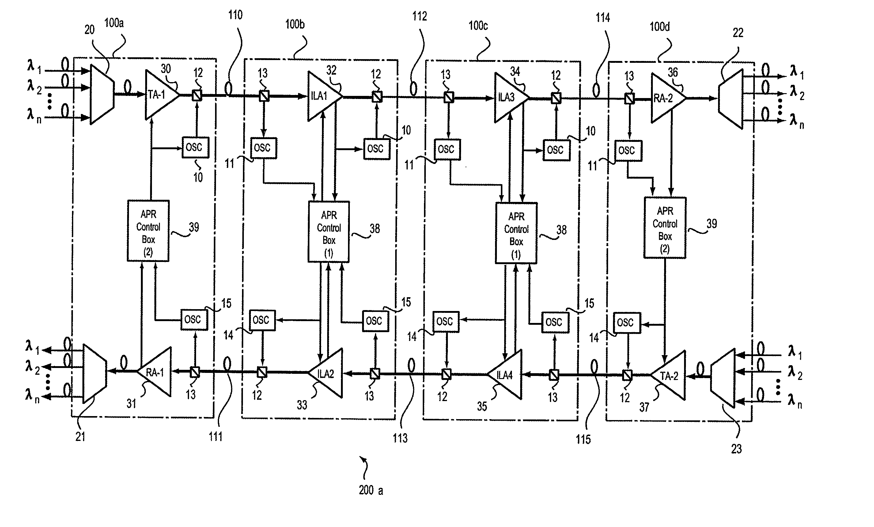
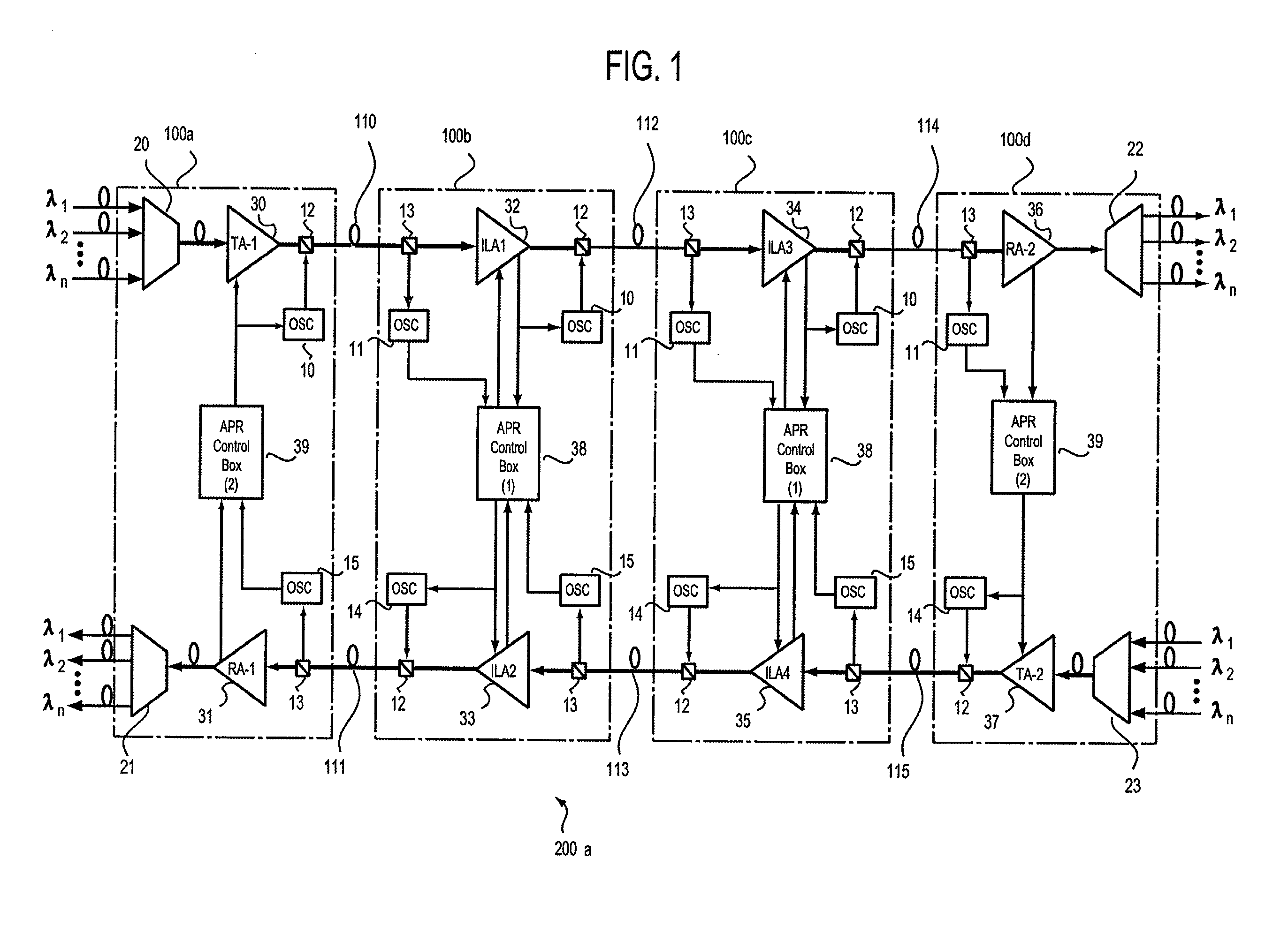
[0099] FIG. 1 is an illustration of a configuration of an optical transmission system according to the present invention. In FIG. 1, an optical transmission system, designated at reference numeral 200a, is for transmitting wavelength-multiplexed light, and is made up of WDM terminal stations 100a and 100d, repeater stations 100b and 100c, optical transmission lines 110, 112 and 114, and optical transmission lines 111, 13 and 115. In this optical transmission system 200a, two kinds of light: main signal light (WDM light) and sub-signal light (OSC light) are transmitted in a state multiplexed with each other.

[0100] The optical transmission lines (up-direction optical transmission lines) 110, 112 and 114 are for up-direction transmission, while the optical transmission lines (down-direction optical transmission lines) 111, 113 and 115 are for down-direction transmission. Moreover, each of these lines is composed of a fiber which is connected to amplifiers placed in each station, thus a...

second embodiment

(B) Description of Second Embodiment of the Invention

[0221] This embodiment employs an ALS method as the laser safety control manner. This ALS method is such that its pertaining station stops the up-direction WDM light output when the downstream side detects WDM-LOL so that the downstream stations successively detect the WDM-LOL, that is, the WDM-LOL is communicated stepwise to the downstream stations. Finally, the last WDM terminal station 110d in the downstream direction stops the output of an opposite side amplifier 37 when detecting the WDM-LOL.

[0222] FIG. 9 is an illustration of a configuration of an optical transmission system according to the second embodiment of the present invention. In FIG. 9, an optical transmission system, denoted at 200b, is for transmission of wavelength-multiplexed light, and is made up of WDM terminal stations 110a and 110d, repeater stations 110b and 110c, optical transmission lines 110, 112 and 114, and optical transmission lines 111, 113 and 115. ...

third embodiment

(C) Description of Third Embodiment of the Invention

[0335] This embodiment employs an APSD method as the laser safety control method, and when detecting WDM-LOL, an amplifier of a repeater station on the downstream side of a trouble occurrence place is made to stop the WDM light output of a down-direction opposite amplifier. In this APSD method, as with the ALS method, a stop of the WDM light output takes place only in a zone in which a fiber trouble has occurred, without spreading to the next station.

[0336] FIG. 20 is an illustration of a configuration of an optical transmission system according to a third embodiment of the present invention. In FIG. 20, an optical transmission system, designated generally at reference numeral 200c, is for transmission of wavelength-multiplexed light, and is made up of WDM terminal stations 120a and 120d, repeater stations 120b and 120c, optical transmission lines 110, 112 and 114, and optical transmission lines 111, 113 and 115. In the illustratio...


PUM


Abstract

The present invention relates to an optical level control method for use in an optical transmission system. In the system, a WDM terminal comprises a multiplexing/demultiplexing unit, an amplifier, an up-direction OSC light transmitting/receiving unit, an up-direction multiplexer, an up-direction branching unit, an amplifier and an APR control unit, and a repeater comprises an up-direction branching unit, an OSC light transmitting/receiving unit, an amplifier, an up-direction multiplexer, a down-direction branching unit, an amplifier, a down-direction multiplexer and an APR control unit. In this configuration, a flexible optical output level control in connection with variation in WDM light level, a selective value irrespective of occurrence of an error stemming from the passage of time and avoidable malfunctions are respectively capable. In addition, a trouble retrieving operator can eliminate the possibility of being exposed to the WDM light.

Description

[0001] (1) Field of the Invention[0002] The present invention relates to an optical level control method suitable, for example, for use in a wavelength multiplexing optical transmission system.[0003] (2) Description of the Related Art[0004] In the recent years, high-speed data communications have encountered a striking increase in communication traffic, and for long-distance transmission, a wavelength multiplexing optical transmission network system (which will sometimes be referred to hereinafter as an "optical transmission system") employing the wavelength division multiplexing (WDM) has been in increasing demand. In this optical transmission system, the distance between stations (offices), such as from a starting-point station to a repeater station, from a repeater station to a repeater station or from a repeater station to an end-point station, has frequently exceeded 600 km. For this reason, the optical transmission system has been put in operation by amplifying the optical out...

Claims


Application Information

Patent Timeline
Patent Type & Authority Applications(United States)
IPC IPC(8): H04B10/00H04B10/03H04B10/07H04B10/077H04B10/079H04B10/29H04B10/294H04B10/297H04B17/40H04J14/00H04J14/02H04L69/40
CPCH04B10/03H04B10/0777H04B10/2918H04B2210/078H04B2210/08H04J14/0221H04B10/298
Inventor IWAKI, HIROYUKIWADA, TETSUO
Owner FUJITSU LTD
Why Eureka
Try Eureka