Vibration damper

a vibration damper and damper technology, applied in the field of vibration dampers, can solve the problem of clear audible operating noises

Inactive Publication Date: 2002-03-07
ZF FRIEDRICHSHAFEN AG
View PDF0 Cites 55 Cited by
  • Summary
  • Abstract
  • Description
  • Claims
  • Application Information

AI Technical Summary

Problems solved by technology

A problem in a damper arrangement of this kind consists in that clearly audible operating noises occur.

Method used


Image

  • Vibration damper
  • Vibration damper
  • Vibration damper

Examples


Embodiment Construction

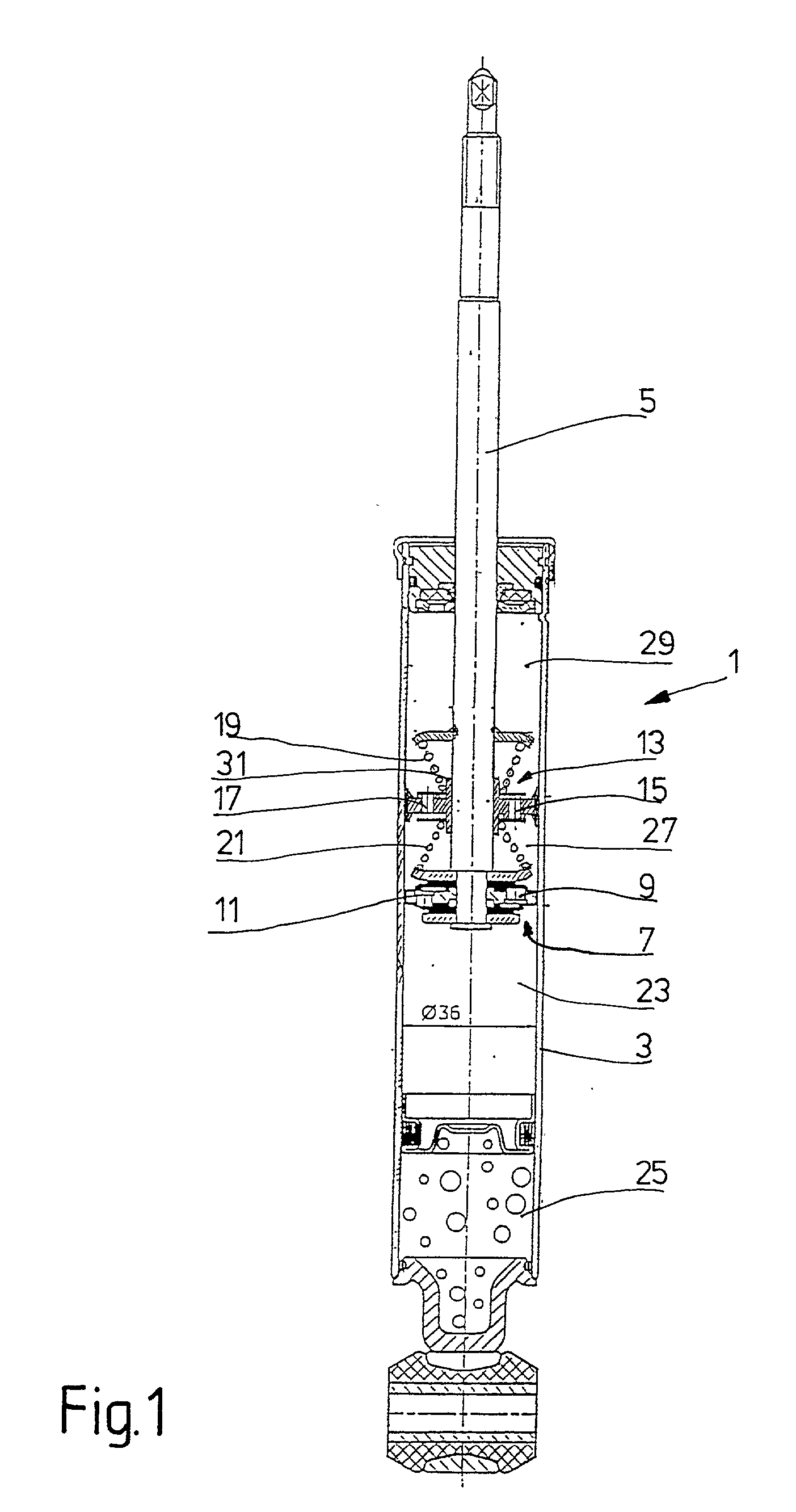
[0026] FIG. 1 shows a vibration damper 1 in mono-tube construction which has a cylinder 3 in which a piston rod 5 is guided so as to be movable axially. In principle, the invention is not limited to use in a mono-tube vibration damper.

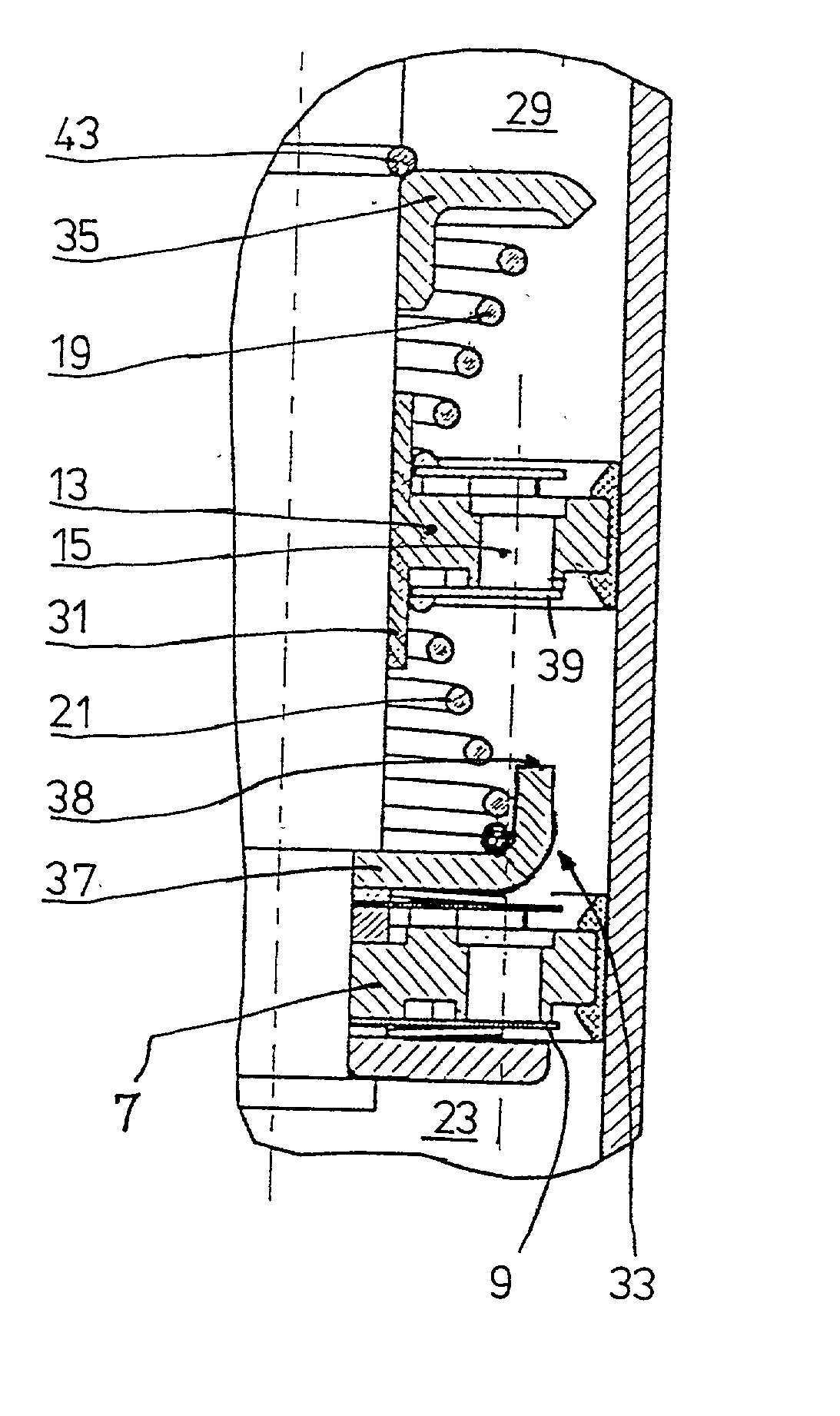
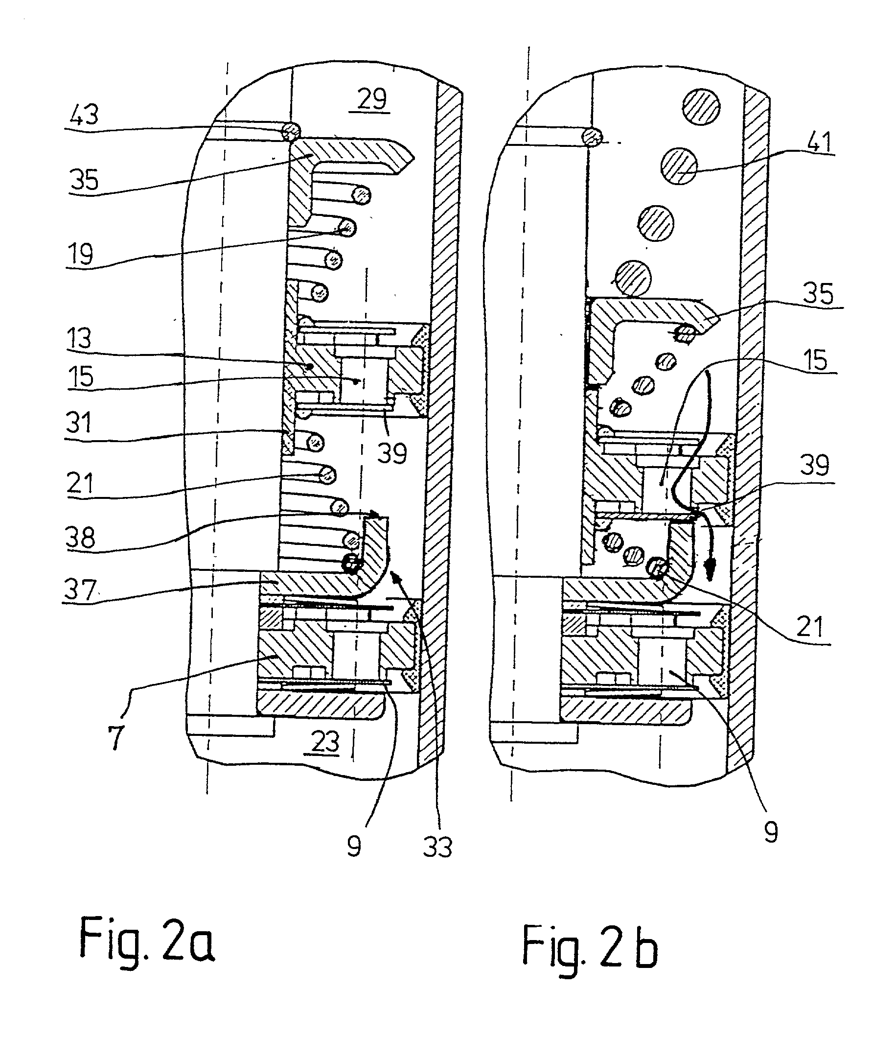
[0027] A first piston 7 is arranged in a stationary manner at the piston rod 5. The piston has through-openings which are outfitted with damping valves 9; 11. A piston of this kind is known, for example, from DE 197 35 249 C1 or DE 197 35 248 C1 and the contents of these two patents make up part of this specification with respect to the construction of the first piston.

[0028] In addition to the stationary first piston 7, a second axially movable piston 13 is arranged at the piston rod 5. With respect to its damping valves 15; 17, the construction of the second piston 13 substantially corresponds to that of the first piston 7. Two return springs 19; 21 hold the second piston 13 in a normal position when the piston rod is stationary.

[0029] The cylinder h...


PUM


Abstract

A vibration damper includes a cylinder in which a piston rod is guided so as to be axially movable. A first piston is mounted stationary on the piston rod and a second piston is mounted so as to be displaceable axially on the rod against a spring force. The cylinder has a work space at the piston rod side, a work space remote of the piston rod, and a work space between the two pistons. Through-openings which are outfitted with valves control a connection between the work spaces. The second piston has at least one return spring on both sides, and the piston is mounted so as to be displaceable axially in two directions against the return springs.

Description

[0001] 1. Field of the Invention[0002] The invention is directed to a vibration damper of the type wherein a piston rod moveable in a cylinder has a first piston mounted stationary thereon and a second piston axially displaceable on the piston rod against a spring force. The cylinder includes a piston rod side work space, a work space remote from the piston rod and a work space between the two pistons. The pistons are provided with valves for connecting the work spaces.[0003] 2. Description of the Related Art[0004] DE-OS 22 30 975 discloses a vibration damper for motor vehicles which has a first stationary piston at a hollow piston rod and a second piston which is displaceable axially against a spring force. The two pistons have through-openings which are outfitted with check valves. The damping force of the vibration damper is generated by a central, double-action damping valve inside the piston rod. The check valves in the pistons serve only to provide damping medium to a work spa...

Claims


Application Information

Patent Timeline
Patent Type & Authority Applications(United States)
IPC IPC(8): F16F9/32F16F9/06F16F9/508F16F9/512
CPCF16F9/061F16F9/5126
Inventor GRUNDEI, MANFRED
Owner ZF FRIEDRICHSHAFEN AG
Why Eureka
Try Eureka