Needleless method and apparatus for transferring liquid from a container to an injecting device without ambient air contamination

a technology of liquid transfer and ambient air, which is applied in the direction of packaging foodstuffs, pharmaceutical containers, packaged goods, etc., can solve the problems of limited value of indicia on the cap and cannot be reattached, so as to avoid the possibility of both unwanted contamination and reduce the amount of time , the effect of eliminating the fear

Inactive Publication Date: 2002-03-28
CATALENT USA WOODSTOCK INC +3
View PDF0 Cites 83 Cited by
  • Summary
  • Abstract
  • Description
  • Claims
  • Application Information

AI Technical Summary

Benefits of technology

[0032] It is a further object of the present invention to provide a device and method as characterized above which reduces the amount of time which hospital staff must spend in transferring fluid from a sterile ampule to a hypodermic syringe while also eliminating the fear of an inadvertent needle stick thereby avoiding the possibility of both unwanted contamination and unwanted medication.
[0040] Viewed from a second vantage point, it is an object to provide a method for transferring injectable fluids from a storage ampule or vial to a needleless syringe or other injecting device using a male luer fitting or other fitting. The syringe has a first coupling and an opening which communicates within an interior cylindrical hollow of the syringe so that fluid passes by the first coupling through the opening and into the hollow to load the syringe. The steps include providing a vial filled with fluid and with an outlet which has a second coupler defining the outlet. The vial is sealed by occluding the coupler outlet with a cap Subsequently, removing the cap and orienting the first and second couplers into complemental fluid tight docking arrangement (so that the opening of the vial registers with the opening of the syringe) allows transfer of the contents of the vial to the syringe without the need for a traditional needle extraction system.

Problems solved by technology

Thus, once the cap has been removed from the bottle, it is never possible to be reattached.
Thus, any indicia on the cap has limited value because it cannot be reassociated with the syringe that contains the contents heretofore in the vial.

Method used


Image

  • Needleless method and apparatus for transferring liquid from a container to an injecting device without ambient air contamination
  • Needleless method and apparatus for transferring liquid from a container to an injecting device without ambient air contamination
  • Needleless method and apparatus for transferring liquid from a container to an injecting device without ambient air contamination

Examples


Embodiment Construction

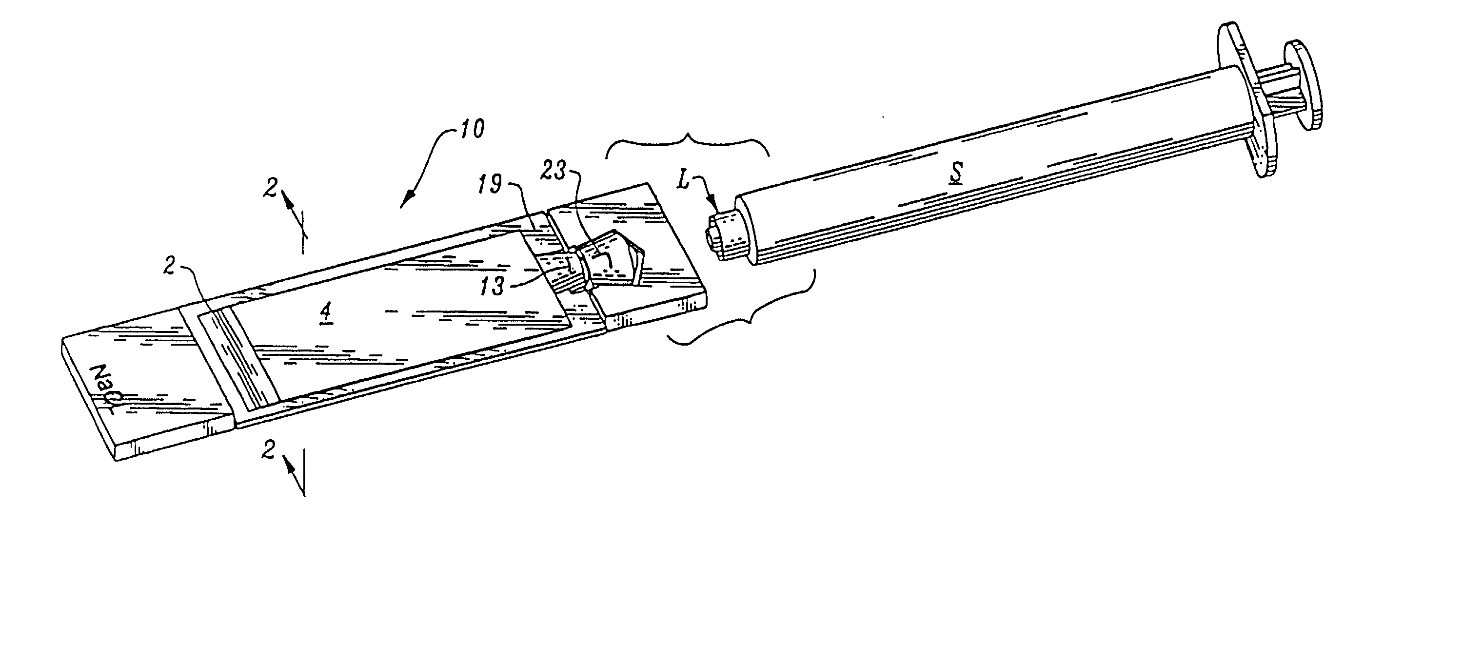
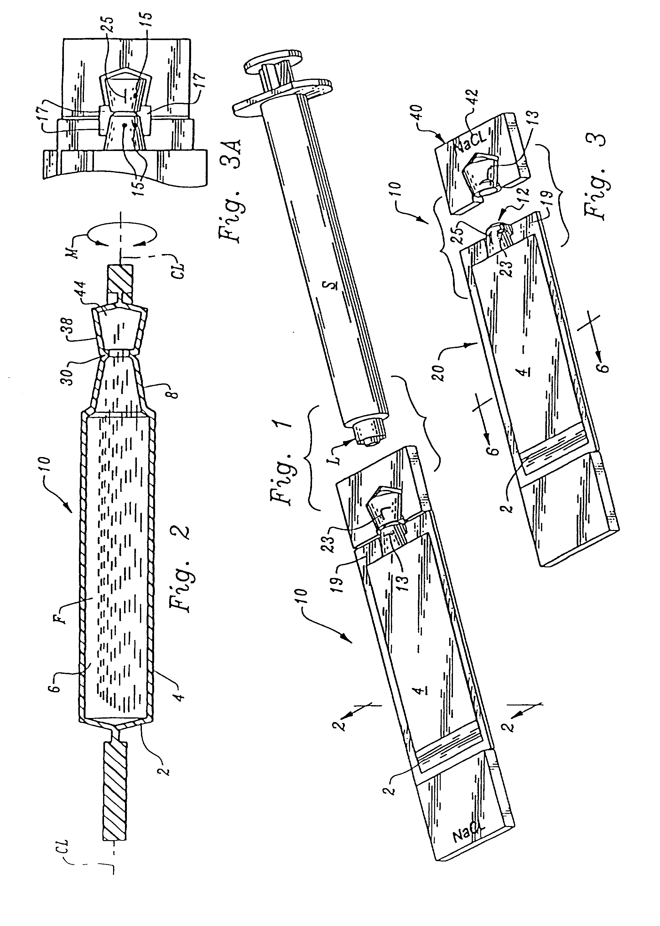
[0070] Referring to the drawings now, wherein like reference numerals refer to like parts throughout the various drawing figures, reference numeral 10 is directed to the vial or ampule according to the present invention.

[0071] In its essence, the vial 10 is formed from two parts: a body portion 20 and a cap portion 40. An area of transition noted as a scoreline 30 serves as an area of demarcation between the cap 40 and body 20. The scoreline 30 allows the cap 40 to be dissociated from the body 20 so that the body 20 can dock with a syringe S as shown in FIGS. 1, 4 and 5 for filling the syringe S with a fluid F contained within the body 20 of the vial 10.

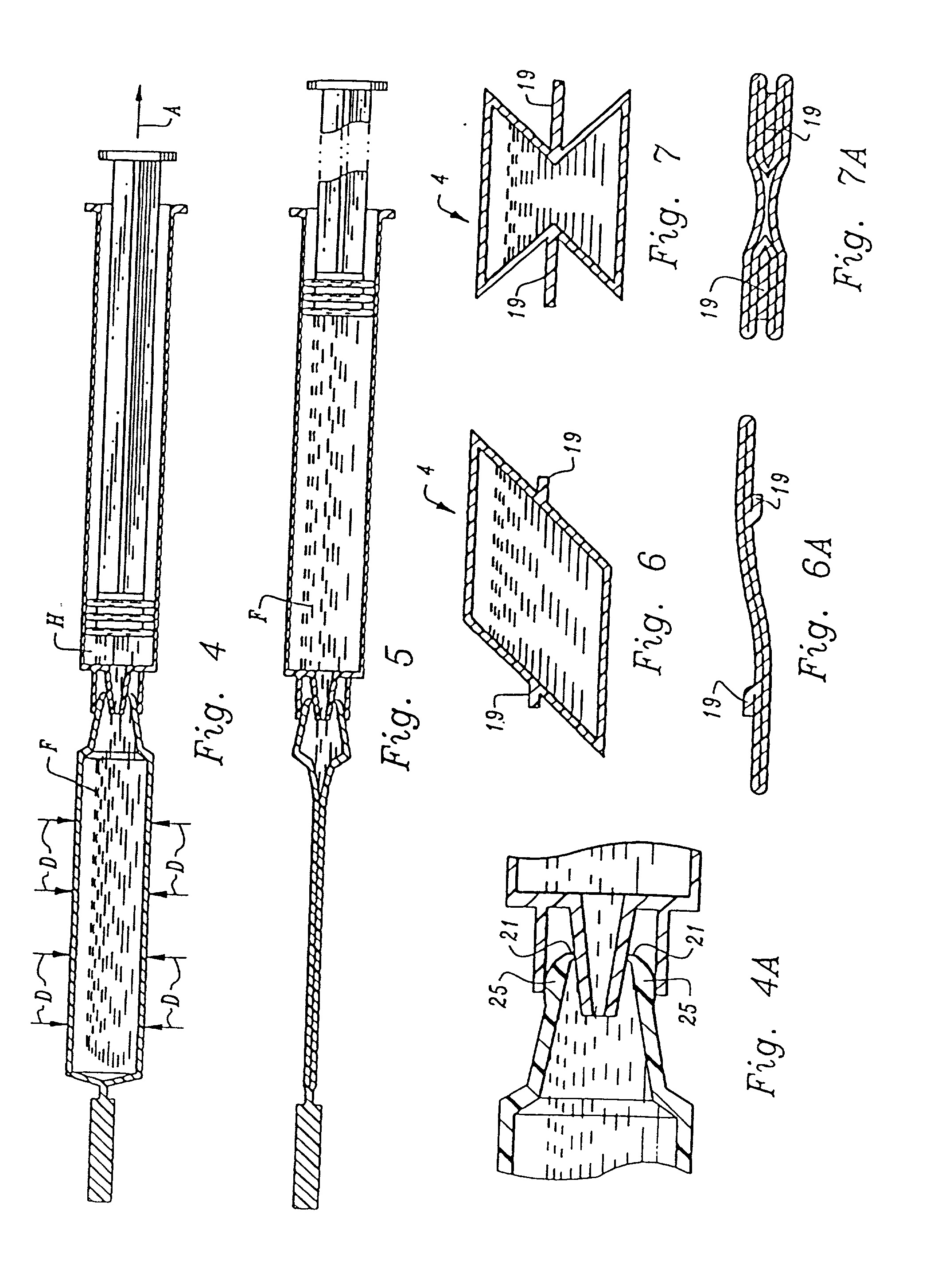
[0072] More specifically, and referring to the drawings in detail, the vial 10 includes a body 20 having an end wall 2, and an enclosing sidewall 4. The peripheral side wall 4 has one proximal end coterminus with an outer periphery of the end wall 2 and extends away from the end wall 2 so that a blind bore 6 has been formed within wh...


PUM

PropertyMeasurementUnit
included angleaaaaaaaaaa
cross-sectional areaaaaaaaaaaa
forceaaaaaaaaaa

Abstract

An ampule having flexible walls with a zone which is programmed to promulgate collapse. The ampule includes an opening that is adapted to dock with a fluid receiving device such as a syringe in air tight sealing engagement. The collapse of the ampule is engineered to occur before breaking the seal that exists between the opening of the ampule and the docking syringe luer tip to ensure sterile transfer of fluid without contamination, especially from ambient air.

Description

[0001] The following invention relates generally to a method and apparatus for transferring fluid from a deformable ampule or vial into a syringe, injecting system (IS) or cannula without the need for a needle. More specifically, a male and female docking arrangement is disclosed coupled with structure for storing and transferring liquids so that the number of times needles are used in a medicating situation is kept to a minimum. The ampule has a structure which docks with the syringe, (IS) or cannula in a fluid tight sealing arrangement and the ampule is designed to collapse easily when extracting a substance such as liquid therefrom so as to preserve the fluid tight seal and therefor not allow air into the ampule, or syringe, or injecting system during the collapsing phase.[0002] Diseases such as nosocomial infections, hepatitis and AIDS, which are pathogens that can be transmitted with the body fluids of a person, are running rampant globally. As a result, medical environments su...

Claims


Application Information

Patent Timeline
Patent Type & Authority Applications(United States)
IPC IPC(8): A61J1/00A61J1/06A61J1/20
CPCA61J1/067A61J1/10A61J1/2096A61J2001/2027A61J1/2055
Inventor FARRIS, BARRY
Owner CATALENT USA WOODSTOCK INC
Why Eureka
Try Eureka