Data storage array device and data access method

a data storage array and data access technology, applied in the direction of generating/distributing signals, instruments, television systems, etc., can solve the problems of significant delay in access requests, limited delay after the disks begin to respond, and inability to access continuous media data uninterruptedly

Inactive Publication Date: 2002-04-04
PANASONIC CORP
View PDF0 Cites 17 Cited by
  • Summary
  • Abstract
  • Description
  • Claims
  • Application Information

AI Technical Summary

Problems solved by technology

Accessing continuous media data requires uninterrupted access to the data in data storage devices and reliability with which the server system as a whole does not stop even if a part of the data storage devices goes wrong.
However, a server system for continuous media is not allowed to cause significant delay with respect to access requests from a host even if it may not be regarded as a failure, because delay above a certain level causes discontinuity of images.
Thus, the delay after the disks begin to respond can be limited to a certain range.
However, the conventional data storage array devices have the problems described below.
However, in the conventional examples, timer processing is performed in which requests and responses are in one-to-one correspondence, so that it is impossible to queue a plurality of requests from the host.
However, it is difficult for the conventional methods using a timer to guarantee the response delay times imply by queuing accesses to the disk devices.
For example, if the access time is guaranteed for the maximum number of requests acceptable at a time, the timer will be set long and therefore the response delay time will belong with no guarantee of real time operation.
Further, when there are a small number of users, only a few requests are accepted at a time and the waiting time will be wasted.

Method used


Image

  • Data storage array device and data access method
  • Data storage array device and data access method
  • Data storage array device and data access method

Examples


embodiment 1

[0058] Embodiment 1

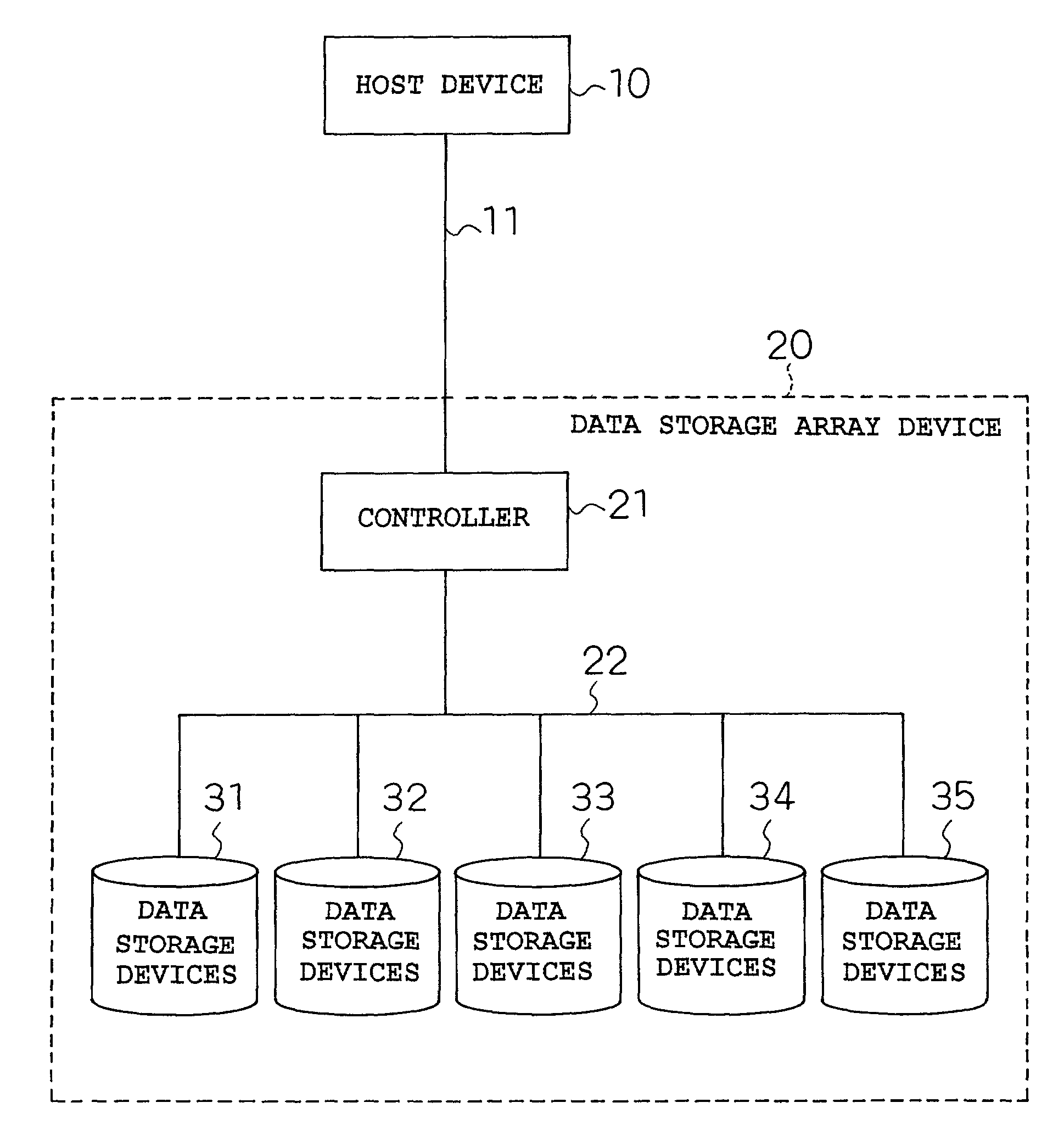
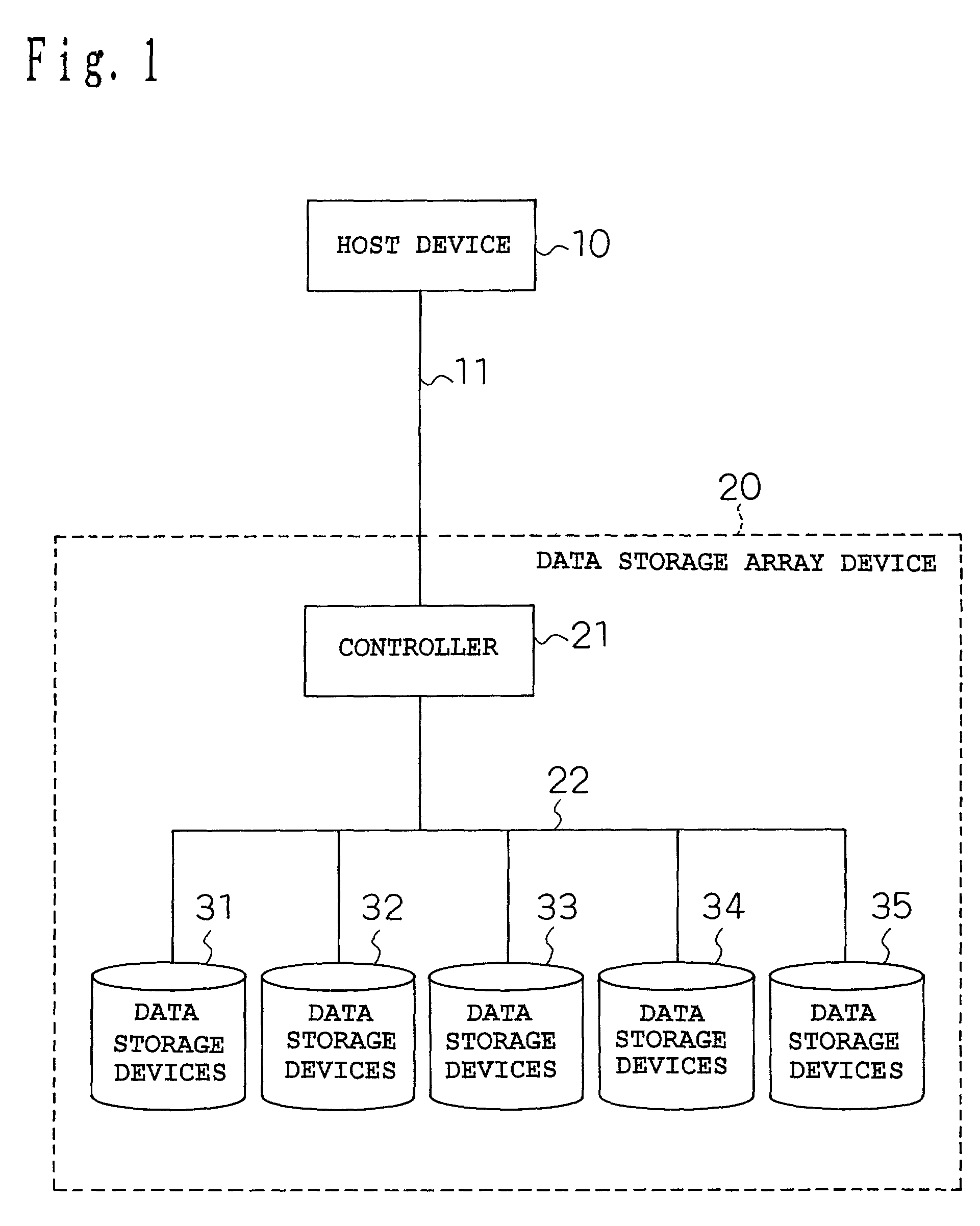
[0059] Now, the operation of the data storage array device will be described according to FIGS. 3 to 6.

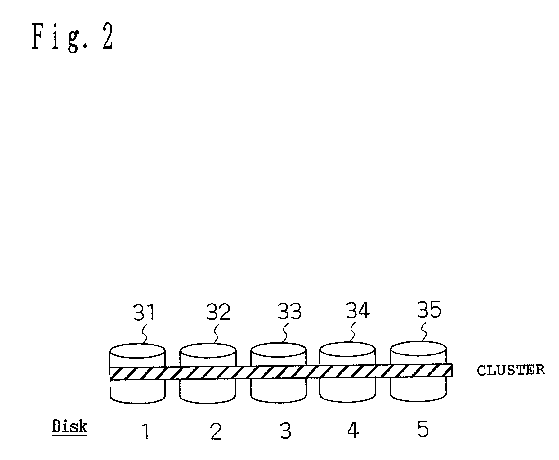
[0060] FIG. 3 is a time chart from the point when the host device 10 requests accesses to the point when responses are completed, in which the number of commands to be queued is three. In this figure, the access requests from the host device 10 are identified with the symbol A, B, and C. FIG. 5 shows steps from the receipt of the access requests to the issue of instructions to the Disks 1 to 5. It is checked that the number of the requests from the host does not exceed the upper limit of queuing (three in this case), and if it does not, the requests are accepted and the instructions to access Disk 1 to 5 are generated. In the case of writing, redundant data is generated and a plurality of instructions to write data and redundant data are generated. In the case of reading out, a plurality of instructions to read out data from the Disks 1 to 5 constituting a cluste...

embodiment 2

[0072] Embodiment 2

[0073] Now, an exemplary operation for isolating the start of response detection for each instruction group from each other will be described by using FIG. 7. In FIG. 7, the timings to start response detection (to start the timer) vary. For each instruction group, the response detection for the instruction group is started (the timer is started) at the time when one of the instructions belonging to the instruction group first begins to be executed in one of the Disks 1 to 5. In this case, the response detection is executed independently for each instruction group, and the timer is also counted separately for each instruction group. For the instruction group B, one of the instructions first begins to be executed in the Disk 2, therefore the response detection is started at the point. The details of the response detection are the same (FIG. 6). This operation has the same advantages as those of the operation of FIG. 3, but it also realizes earlier responses in appli...


PUM


Abstract

A data storage array device including: a plurality of data storage devices having a redundant information; and a controller that controls the data storage devices, wherein the controller has instruction issuing means of sequentially issuing access instruction groups configured by a plurality of divided access instructions, to the plurality of data storage devices; response detecting means of detecting responses to the instructions executed in the data storage devices; timer means of counting time; and completion processing means, which monitors a group of responses to a given one of the access instruction groups, and if the responses from all data storage devices have been finished within a period set by the timer means, completes response processing for the given one of the access instruction groups at the point when the responses have been finished, and if the responses from all data storage devices have not been finished at the end of a period set by the timer, completes response processing for the given one of the access instruction groups by using only the responses from the data storage devices that have finished their responses at the end of the period of the timer.

Description

[0001] 1. Field of the Invention[0002] The present invention relates to a data storage array device having a redundant configuration and so on for storing continuous media data such as image information.[0003] 2. Related Art of the Invention[0004] With the recent development in multimedia technology, continuous media data such as digital images and voice data are more often recorded onto data storage devices (random access devices) such as a hard disk drive. For image data, such as MPEG for example, the transfer rate is about 1.5 to 30 Mbps per stream. Further, since the data size of continuous media data is large, it is becoming common to use several random access devices as an array, and to allow them to be externally recognized as one virtual large-capacity device.[0005] Accessing continuous media data requires uninterrupted access to the data in data storage devices and reliability with which the server system as a whole does not stop even if a part of the data storage devices g...

Claims


Application Information

Patent Timeline
Patent Type & Authority Applications(United States)
IPC IPC(8): G06F3/06G06F11/10G06F12/00G06F13/00H04N5/00H04N7/173
CPCG06F3/0611G06F3/0659G06F3/0689G06F11/1076H04N21/2396G06F2211/1016H04N7/17336H04N21/2312H04N21/2326G06F11/1088
Inventor NISHIKAWA, JUNJIMIGITA, MANABU
Owner PANASONIC CORP
Why Eureka
Try Eureka