Antenna apparatus and a portable wireless communication apparatus

a wireless communication and antenna apparatus technology, applied in the direction of resonant antennas, elongated active elements, independent non-interacting antenna combinations, etc., can solve the problems of unbalanced feed of monopole antennas with respect to the ground plane, and insufficient actual pag

Inactive Publication Date: 2002-04-11
PANASONIC CORP
View PDF0 Cites 60 Cited by
  • Summary
  • Abstract
  • Description
  • Claims
  • Application Information

AI Technical Summary

Problems solved by technology

This monopole antenna is fed in an unbalanced condition with respect to the ground plane.
Thus, if the portable wireless communication apparatus is used with inclination, the main polarizing direction is also inclined, so that the actual PAG was insufficient.

Method used


Image

  • Antenna apparatus and a portable wireless communication apparatus
  • Antenna apparatus and a portable wireless communication apparatus
  • Antenna apparatus and a portable wireless communication apparatus

Examples


first embodiment

[0061] An antenna apparatus will be described with reference to FIGS. 1 to 8. In this embodiment, it is assumed that the operation frequency of the antenna apparatus is 2 GHz.

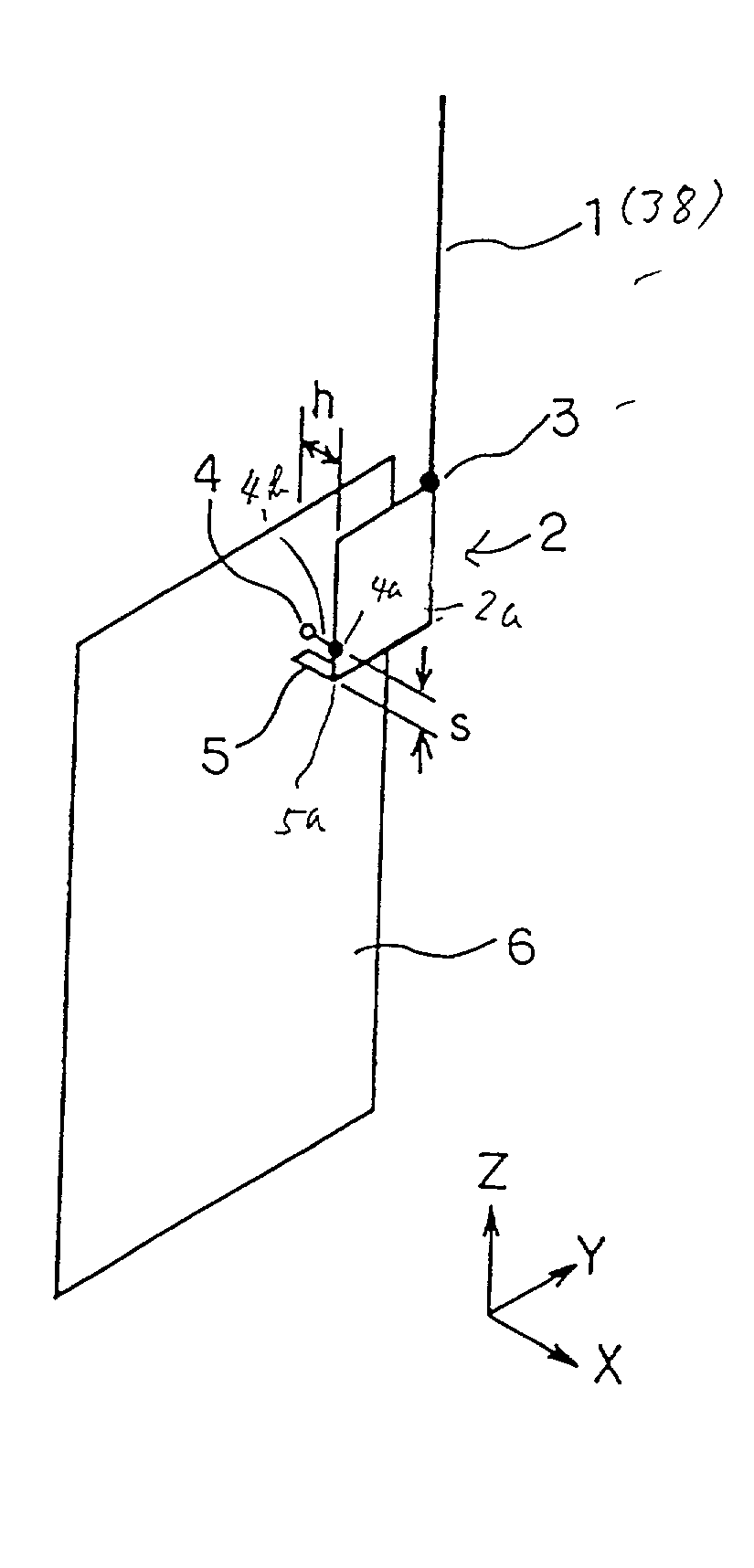
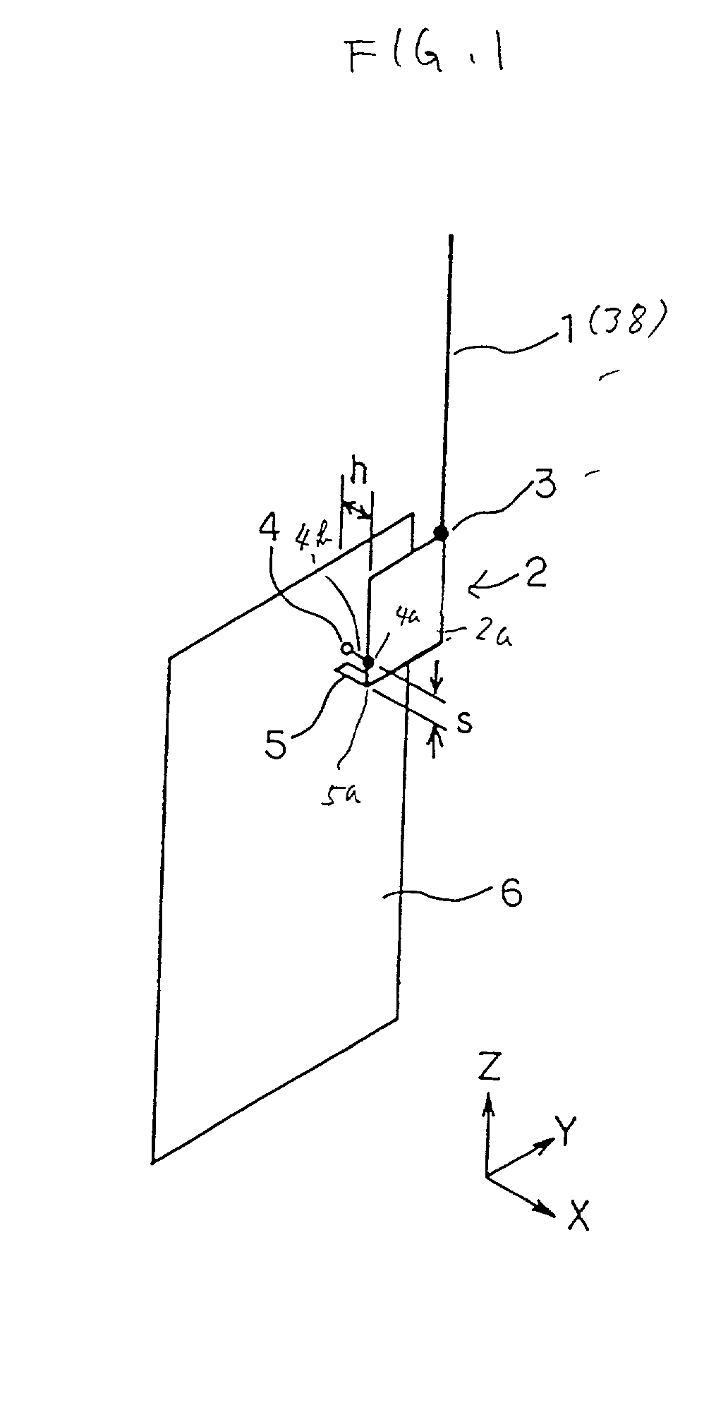
[0062] FIG. 1 is a perspective view of the antenna apparatus of the first embodiment. A monopole 1 has a half wavelength (75 mm) at the operation frequency and acts as a monopole element protruding from a portable wireless communication apparatus.

[0063] A planer inverted-F antenna 2 includes a square conductor plate 2a having a peripheral length (75 mm) which is about a half wavelength of the operation frequency of the antenna apparatus. The square conductor plate 2a is arranged in parallel to a ground plane 6 at a distance h (for example, 5 mm). A point (corner) of the square conductor plate 2a is electrically connected to the ground plane 6 with a shorting portion 5. That is, the point is grounded as a zero voltage point 5a. At a distance s (for example, 1 mm) from shorting portion 5, a feeding portion 4 is ...

second embodiment

[0076] FIG. 4 is a perspective view of an antenna apparatus according to a

[0077] The antenna apparatus according to the second embodiment is substantially the same as that of the first embodiment. The difference is that an inverted-F antenna 24 replaces the planer inverted-F antenna 2.

[0078] As shown in FIG. 4, the inverted-F antenna 24 includes a conductor plate 24a having a length of about a quarter wavelength (37.5 mm) and a width of 2 mm. The inverted-F antenna 24 is arranged above the ground plane 6 along an edge of the ground plane 6 having a rectangular shape. The distance between the inverted-F antenna 24 and the ground plane 6 is 5 mm for example. One end of the inverted-F antenna 24 is connected to the ground plane 6 through a shorting portion 26. The other end of the inverted-F antenna 24 is connected to one end of the monopole antenna 1. The monopole antenna 1 is perpendicularly arranged to the longitudinal direction of the inverted-F antenna 24.

[0079] As shown in FIG. 4...

fourth embodiment

[0096] As mentioned above, the antenna apparatus provides a directivity diversity operation with the high frequency switch 30.

[0097]

[0098] FIG. 7 is a perspective view of an antenna apparatus according to a fifth embodiment. The antenna apparatus according to the fifth embodiment has substantially the same structure as that of the second embodiment. The difference is that the inverted-F antenna 24 is provided on a printed circuit board 36. The end of the monopole antenna 35 is connected to or contacted to a round 33. The end of the inverted-F antenna 24 is connected to the round 33 by soldering through a conductor 24b. The feeding portion 25 is connected to a round 34 on the printed circuit board 36 by soldering. The other end of the inverted-F antenna 24 is connected to the ground plane 37 with the shorting portion 26.

[0099] The antenna apparatus shown in FIG. 7 operates as same as that of the second embodiment.

[0100] In manufacturing, the inverted-F antenna 24 is soldered and th...


PUM


Abstract

A microstrip antenna (MSA) above a ground plane, having a size corresponding to an operation frequency, at a junction point thereof, electrically connected to one end of a monopole antenna having a size corresponding to the operation frequency to operate as a complex antenna. A distance between the feed point of MSA and the junction point determines the input impedance for matching. A microstrip line or an (planer) inverted-F antenna may provide the MSA. The monopole element may be a monopole antenna or helical antenna. A portable wireless communication apparatus includes the antenna apparatus having a housing. The monopole antenna is connected to the MSA when the monopole antenna is extended from the housing. A switch may be provided between the monopole antenna and the MSA for diversity operation. The antenna apparatus may be formed on a Printed circuit board and folded.

Description

[0001] 1. Field of the Invention[0002] This invention relates to an antenna apparatus and a portable wireless communication apparatus.[0003] 2. Description of the Prior Art[0004] An antenna apparatus including a microstrip antenna is known and a portable wireless communication apparatus including the antenna apparatus including a microstrip antenna is also known.[0005] In a portable wireless communication apparatus (a mobile or base station) of a semi-microwave band, a microstrip antenna or a monopole antenna is used. The microstrip antenna includes a square or a circular planer element above a ground plane at a constant interval. The length of the planer element is generally a half wavelength (referred to as a half wavelength microstrip antenna). This half wavelength microstrip line antenna has directivity in the direction perpendicular to the plane of the microstrip line. The main polarizing direction is single and corresponds to the edge of the microstrip line of which length is ...

Claims


Application Information

Patent Timeline
Patent Type & Authority Applications(United States)
IPC IPC(8): H01Q3/24H01Q1/24H01Q1/36H01Q9/04H01Q9/30H01Q13/08H01Q21/28H01Q21/30
CPCH01Q1/362H01Q9/0421H01Q21/28H01Q9/42H01Q9/30
Inventor SAITOU, YUTAKANISHIKIDO, TOMOAKIHARUKI, HIROSHI
Owner PANASONIC CORP
Why Eureka
Try Eureka