Ultrasound system and ultrasound diagnostic apparatus for imaging scatterers in a medium

a technology of ultrasound diagnostic equipment and ultrasound system, which is applied in the field of ultrasonic system and ultrasound diagnostic equipment for imaging scatterers in a medium, can solve the problems of lowering the diagnostic information of the ultrasonic image, limited penetration depth, and small image dynamic rang

Inactive Publication Date: 2002-04-25
KONINKLIJKE PHILIPS ELECTRONICS NV
View PDF0 Cites 24 Cited by
  • Summary
  • Abstract
  • Description
  • Claims
  • Application Information

AI Technical Summary

Problems solved by technology

A low SNR causes a limited penetration depth and a small dynamic range of the image, thus lowering the diagnostic information of the ultrasonic image.
So, one significant problem is that the maximum duration of coded signals is limited by the propagation period of these coded signals, which is calculated as twice the distance between the probe and the area to be imaged divided by the propagation velocit

Method used


Image

  • Ultrasound system and ultrasound diagnostic apparatus for imaging scatterers in a medium
  • Ultrasound system and ultrasound diagnostic apparatus for imaging scatterers in a medium
  • Ultrasound system and ultrasound diagnostic apparatus for imaging scatterers in a medium

Examples


Embodiment Construction

[0021] The present invention relates to an ultrasound imaging system for imaging ultrasound scatterers in a medium.

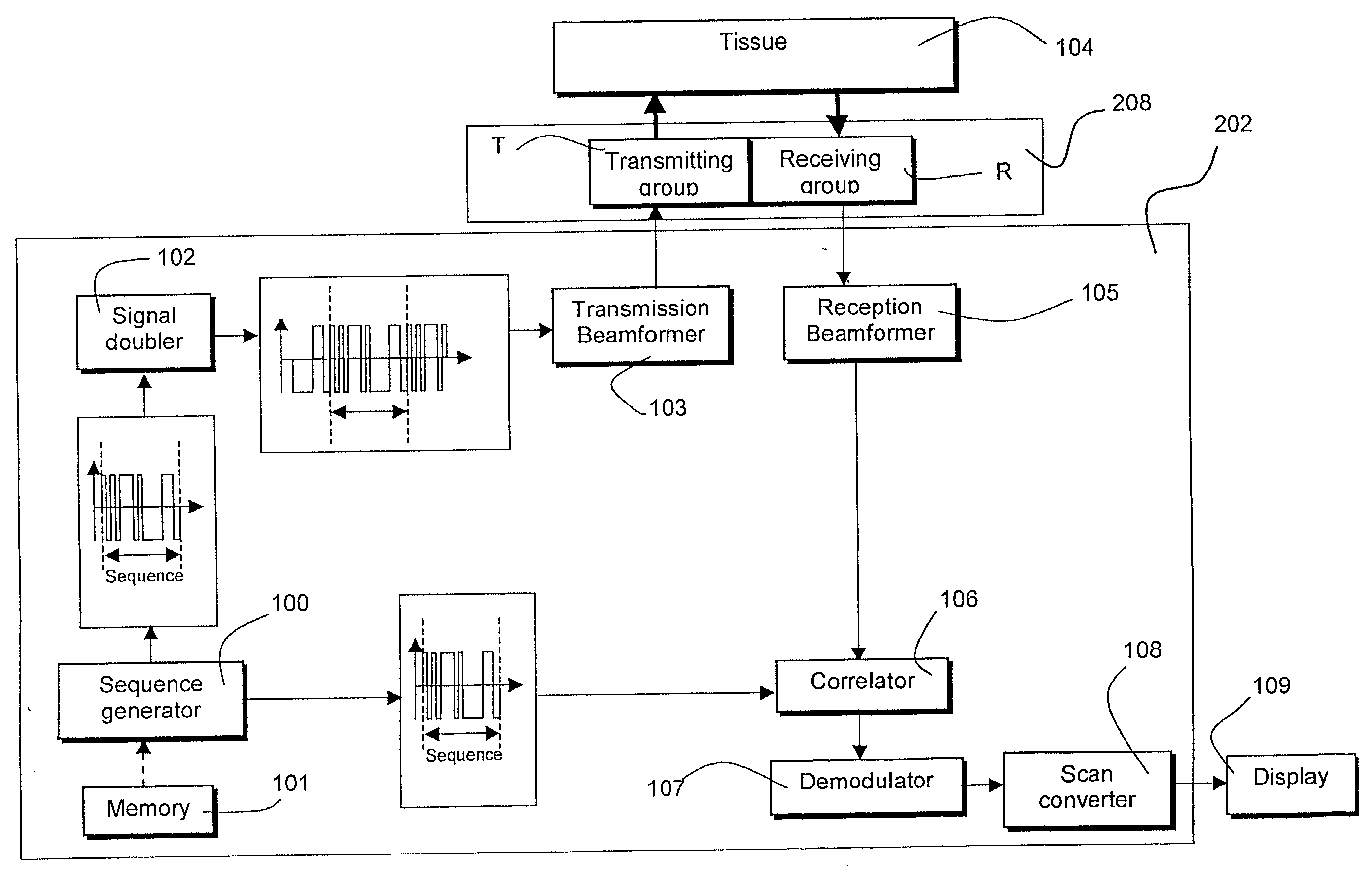
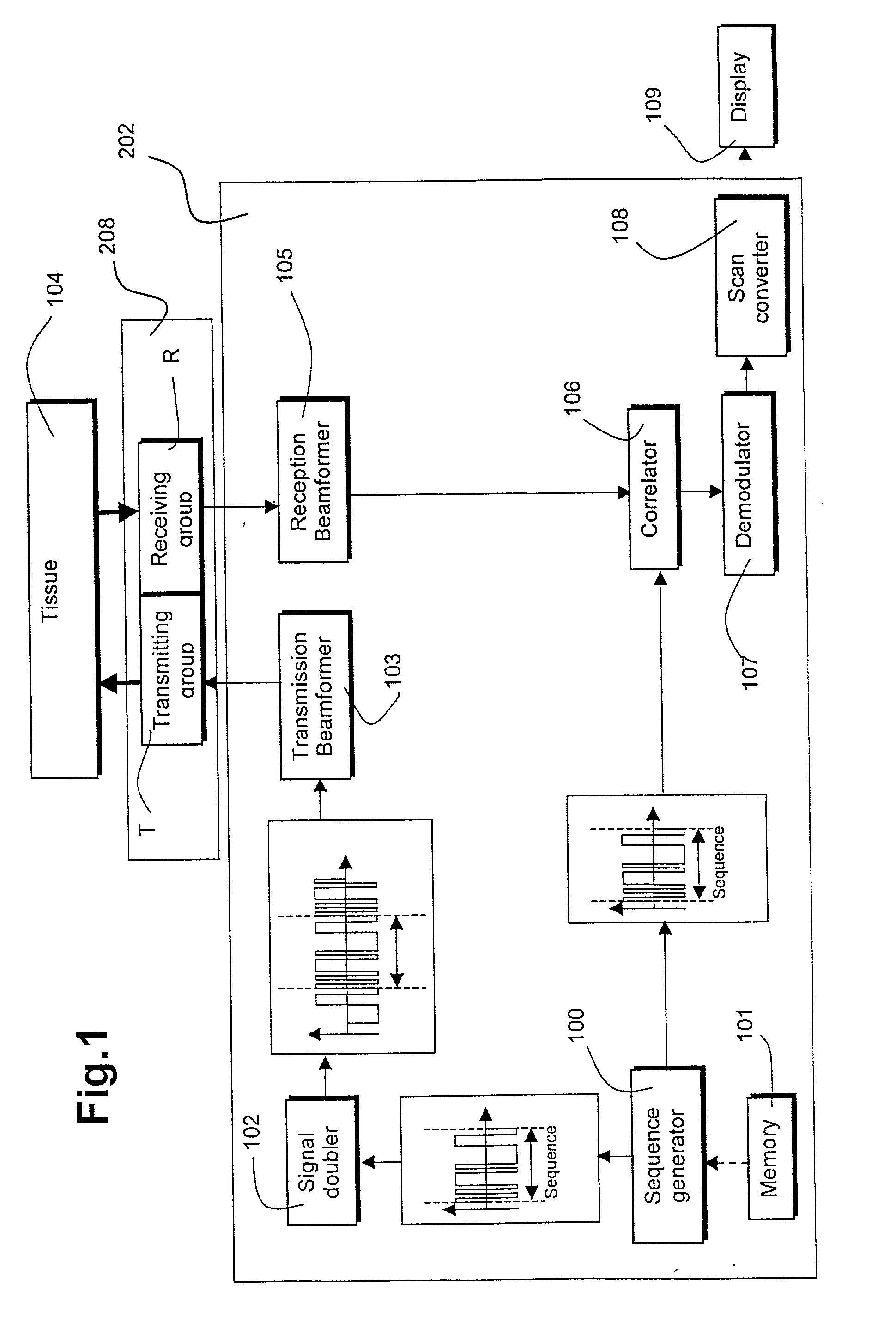
[0022] Referring to FIG. 1, this ultrasound imaging system comprises a probe 203 that comprises two distinct groups of transducer elements: a first group labeled transmitting group T to transmit ultrasound waves and a second group labeled receiving group R for detecting ultrasound echoes reflected by said ultrasound scatterers. In an embodiment of the invention, these two distinct groups can exchange their functions: the original transmitting group serving as receiving group while the original receiving group is serving as transmitting group. In one embodiment, the first and second distinct groups of transducer elements are formed by two distinct transducer arrays. In a particular embodiment, the transmitting group and the receiving group can be each one group of transducer elements belonging to a single transducer. In this case, the two distinct groups of transducer el...


PUM


Abstract

An ultrasound imaging system for imaging ultrasound scatterers, comprising a probe (208) for transmitting ultrasound waves and detecting ultrasound echoes reflected by said ultrasound scatterers, wherein said probe comprises a first group of transducer elements, labeled transmitting group (T), to transmit ultrasound waves, and a distinct second group of transducer elements, labeled receiving group (R), to detect ultrasound echoes reflected by said ultrasound scatterers. The system also comprises a processing system (202) comprising transmission and reception means, coupled to said probe (208), for providing coded signal to said transmitting group (T) and receiving signals from said receiving group (R) respectively; transmission beam-forming means (103) for focussing the ultrasound waves on a focus line, reception beam-forming means (105) for forming beam-summed received signals from signals received from the focus line and processing means for processing said beam-summed received signals to form decoded signals so as; and means for displaying an image (109) that is a function of said decoded signals.

Description

DESCRIPTION[0001] 1. Field of the Invention[0002] The invention relates to an ultrasound system associated with a probe for imaging ultrasound scatterers in a medium. The invention also relates to an ultrasound diagnostic imaging apparatus, including such a system and a probe, for increasing the signal-to-noise ratio (SNR) in medical ultrasound imaging.[0003] 2. Background of the Invention[0004] A method and apparatus for improving the SNR in medical ultrasound imaging is described in the patent U.S. Pat. No. 5,984,869 (Chiao and alii). This document relates to a method and an apparatus that increase the signal-to-noise ratio (SNR) in medical ultrasound imaging by using Golay-coded excitation signals. A low SNR causes a limited penetration depth and a small dynamic range of the image, thus lowering the diagnostic information of the ultrasonic image. This document proposes a solution to obtain a good SNR, which consists in increasing the signal energy. By using coded signals (e.g. ch...

Claims


Application Information

Patent Timeline
IPC IPC(8): G01N29/44A61B8/00B06B1/02G01S7/523G01S7/524G01S15/89
CPCA61B8/00B06B1/023G01S15/8927G01S15/8959G01S15/8915G01S15/8913A61B8/4494
Inventor ECK, KAISCHMITZ, GEORG
Owner KONINKLIJKE PHILIPS ELECTRONICS NV
Why Eureka
Try Eureka