Digital protective relay system

a relay system and digital technology, applied in the field of protective relays, can solve the problems of reducing the rate of operation, the delay time of transmission to both directions on the transmission line,

Inactive Publication Date: 2002-05-16
KK TOSHIBA
View PDF4 Cites 17 Cited by
  • Summary
  • Abstract
  • Description
  • Claims
  • Application Information

AI Technical Summary

Benefits of technology

[0018] The above sampling synchronizing method requires the addition of data for synchronizing into the transmitted data. Therefore, a first disadvantage of this method is that the transmission delay time to both directions on the transmission lines need to be same for establishing synchronous control between terminals.

Problems solved by technology

Therefore, a first disadvantage of this method is that the transmission delay time to both directions on the transmission lines need to be same for establishing synchronous control between terminals.
Furthermore, a second disadvantage of this method as above mentioned is that the rate of operation lowers because the loss of synchronism happens in response to the fluctuation of the transmission delay time even if the downstream and the upstream transmission delay time on the transmission lines are same.

Method used


Image

  • Digital protective relay system
  • Digital protective relay system
  • Digital protective relay system

Examples


first embodiment

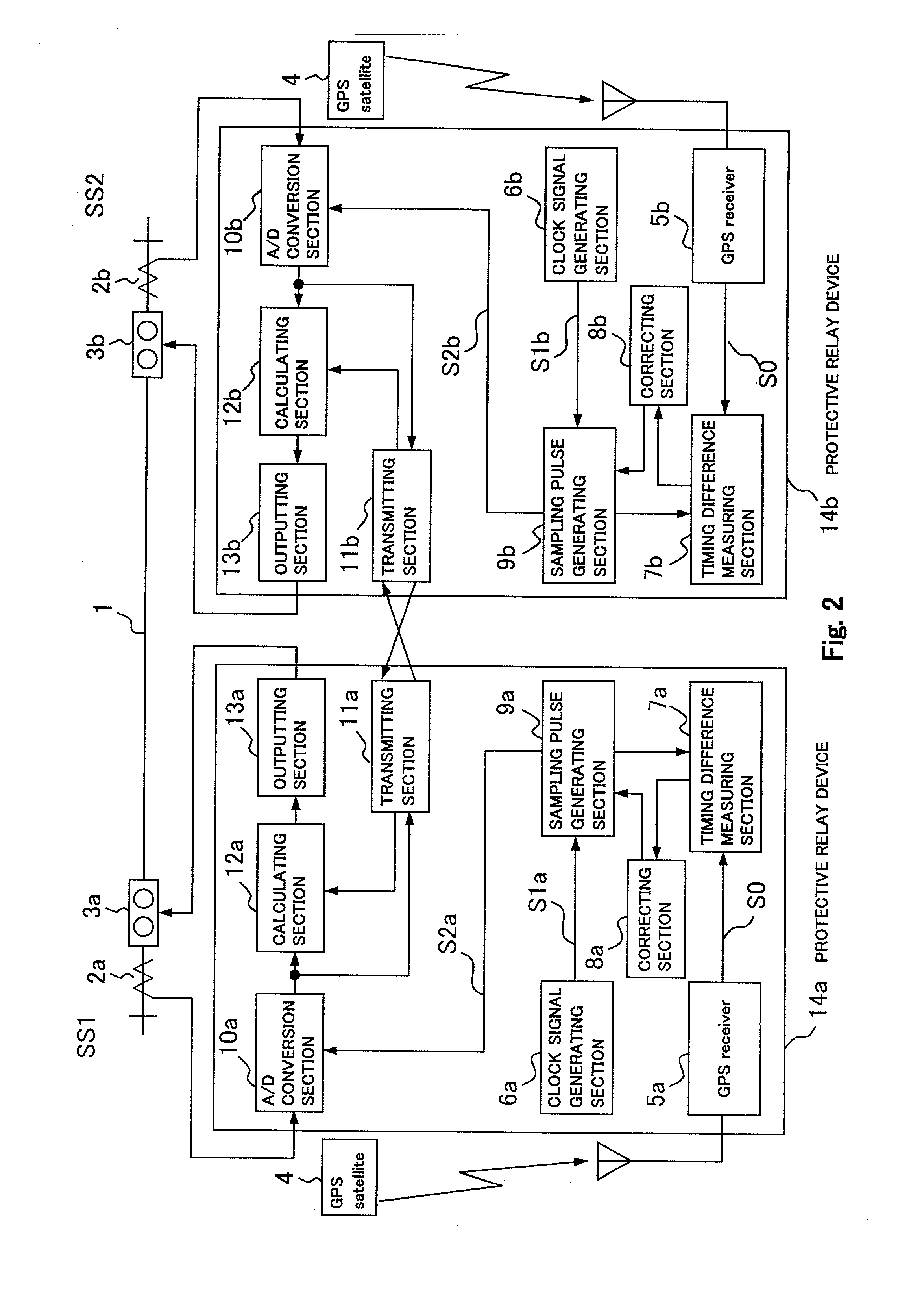
[0043] (First embodiment)

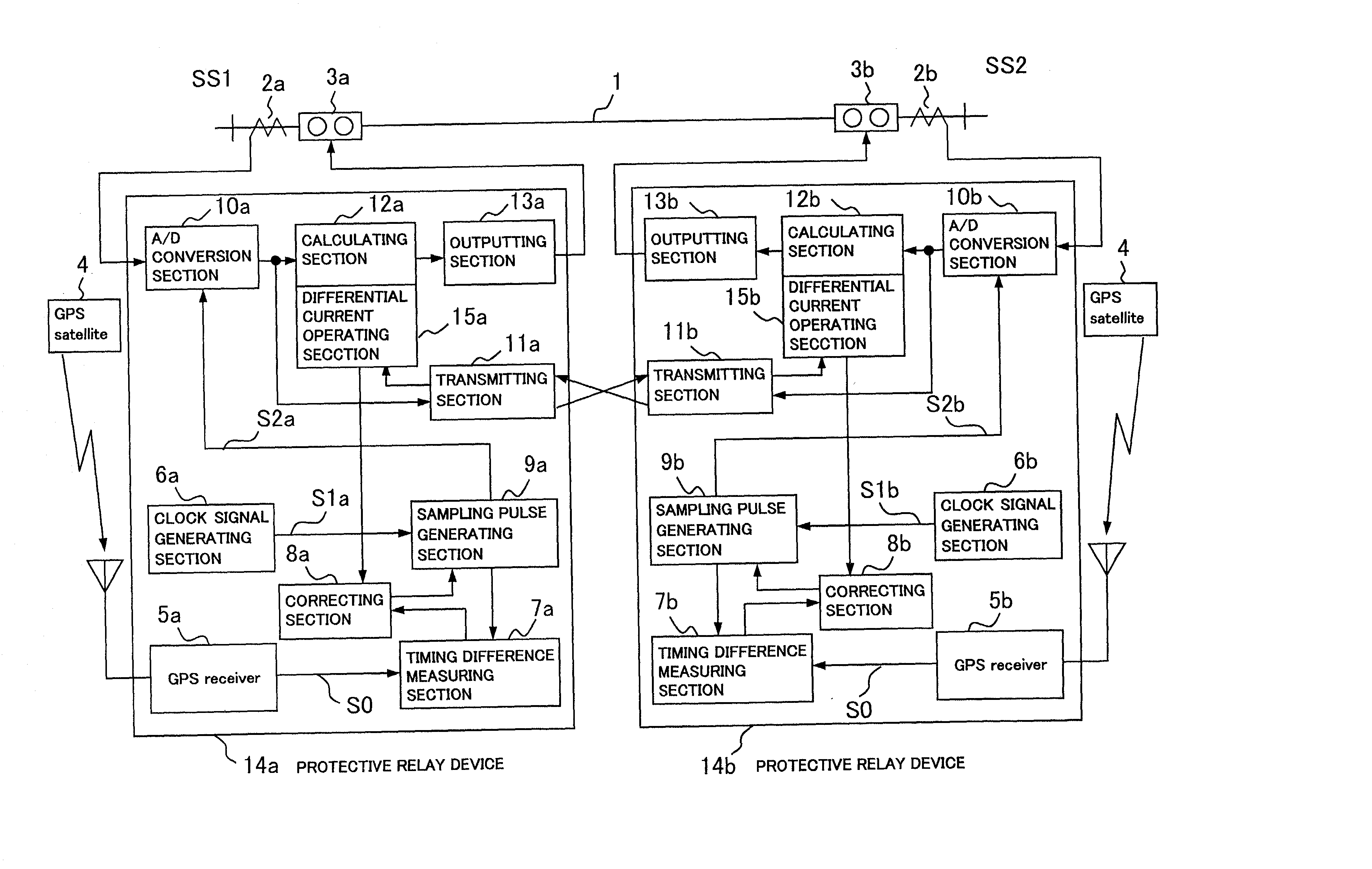
[0044] FIG. 2 shows the diagram showing a first embodiment in accordance with the present invention.

[0045] There is shown a protective relay system protecting a transmission line 1 through a pair of protective relay devices (a protective relay device 14a and 14b), which is provided at a terminal SS1 and a terminal SS2 opposite to each other across the transmission line 1. Provided at the respective terminals are current transformers 2a and 2b for detecting the current through the transmission line 1 and for adjusting the detected current for the protective relay device 14a and 14b, and circuit breakers 3a and 3b that are operative responsive to the protective relay device 14a and 14b.

[0046] The protective relay device 14a and 14b respectively receive the currents from current transformer 2a and 2b, and periodically sample the currents and digitize them to obtain current data through A / D conversion sections 10a and 10b.

[0047] The obtained electrical quantity ...

second embodiment

[0056] (Second embodiment)

[0057] FIG. 4 is a block diagram showing a second embodiment in accordance with the present invention.

[0058] In FIG. 4, the same elements as shown in FIG. 2 are identified with the same reference numerals as used in FIG. 2, and explanation is omitted for the sake of brevity. The difference between the first embodiment and this embodiment is the addition of a differential current operating sections 15a and 15b.

[0059] With the first embodiment, if the timing signals normally output from the GPS satellite 4 are not output for some reason, with the result that the fixed cycle pulse S0 from the GPS receivers 5a and 5b will not be output, the timing difference measuring section 7a and 7b and the correcting section 8a and 8b will not function properly or at all. Therefore, the synchronization will slip gradually by virtue of the deviation between clock signals from the clock signal generating section 6a and 6b.

[0060] This embodiment is based on the principle that ...

third embodiment

[0064] (Third embodiment)

[0065] FIG. 5 is a block diagram of a third embodiment in accordance with the present invention.

[0066] In FIG. 5, the same elements as shown in FIG. 2 are identified with the same reference numerals as used in FIG. 2, and explanation is omitted for the sake of brevity. The difference between the first embodiment and this embodiment is the addition of the differential phase operating sections 16a and 16b.

[0067] With this embodiment, when the synchronization between terminals is established in the state where there is no fault in a power line 1, it operates under the principle that the phase difference of the current at both terminals serves as zero. In more detail, the protective relay device 14a is used as a main terminal, and the protective relay device 14b as a secondary terminal. When the GPS satellite 4 does not output timing signals, or when the fixed cycle pulse S0 is not output from a GPS receivers 5a and 5b, whereby the synchronization between termin...


PUM


Abstract

A digital protective relay system is capable of making sampling timing the same among plural protective relay device which operate independent from each other by using a signal from a GPS satellite. The sampling timing is made the same regardless of the time lag from which it is sent downstream with the concomitant transmission delay time in the case of data communications, or regardless of the time lag from which it is sent upstream.

Description

[0001] 1. Field of the Invention[0002] The present invention relates to a protective relay for synchronizing the sampling of electrical quantity data at a plurality of terminals on an electric power system by using a Global Positioning System, referred to as GPS.[0003] 2. Description of the Related Art[0004] A protective relay system is known in which electrical quantity data, such as electric current, is sampled at a plurality of positions or terminals in an electric power system, such as a power transmission system. Electrical quantity data in digital form obtained by the sampling is exchanged between the terminals and used for calculation for the purpose of providing a protective function for the electrical power system.[0005] In such a system, the sampling at the respective terminals must be synchronized, whereby the time at which the electrical quantity data is sampled at the respective terminals must be made to coincide accurately. This ensures that electrical quantity data ob...

Claims


Application Information

Patent Timeline
Patent Type & Authority Applications(United States)
IPC IPC(8): H02H1/00H02H3/02H02H7/26
CPCH02H7/261H02H1/0061H02H3/28H02H3/02
Inventor SUGIURA, HIDEAKISHUTO, ITSUOITO, HACHIDAISAGA, MASAMICHI
Owner KK TOSHIBA
Why Eureka
Try Eureka