
Method and device for electro microsurgery in a physiological liquid environment

a liquid environment and electro microsurgery technology, applied in medical science, surgical instruments for heating, therapeutic heating, etc., can solve the problems of coagulation in the area surrounding the cut tissue, devices are totally useless for endolaser applications, and the widespread acceptance of dc pulsed electrical methodologies

Inactive Publication Date: 2002-05-23
NANOPTICS
View PDF2 Cites 21 Cited by
  • Summary
  • Abstract
  • Description
  • Claims
  • Application Information

AI Technical Summary

Benefits of technology

Enables precise and efficient microsurgical procedures in physiological media, such as vitreoretinal surgery, with the capability for controlled tissue cutting, coagulation, and electroporation, overcoming the limitations of existing devices by producing sub-millimeter cavitation bubbles and extending device lifespan for repetitive use.

Problems solved by technology

As a result, the only capability of such devices is to cut soft tissues by heat deposition which causes significant coagulation in the area surrounding the cut tissue.
Such devices are totally useless for endolaser applications, for example in the eye.
In addition to such RF techniques, DC pulsed electrical methodologies have not achieved a widespread acceptance because the absence of coagulation was considered an undesirable effect.
However, these techniques, which were designed for relatively high energy pulse generation (tens of milliJoules) with relatively long pulse durations (hundreds of microseconds), were only used as a means for shock wave generation for hard tissue destruction (R. Vorreuther, R. Corleis, T. Klotz, P. Bernards, U. Engelmann, J. Urology 153:849-853 (1995)).
The previous high energy devices described above have a lifetime of less than 100 pulses (R. Vorreuther, R. Corleis, T. Klotz, P. Bernards, U. Engleman, J. Urology 153:849-853 (1995) and this is by far not sufficient for the microsurgical applications that are envisioned.

Method used


Image

  • Method and device for electro microsurgery in a physiological liquid environment
  • Method and device for electro microsurgery in a physiological liquid environment
  • Method and device for electro microsurgery in a physiological liquid environment

Examples


Embodiment Construction

[0012] The foregoing features of the invention are illustrated in the accompanying drawings, in which:

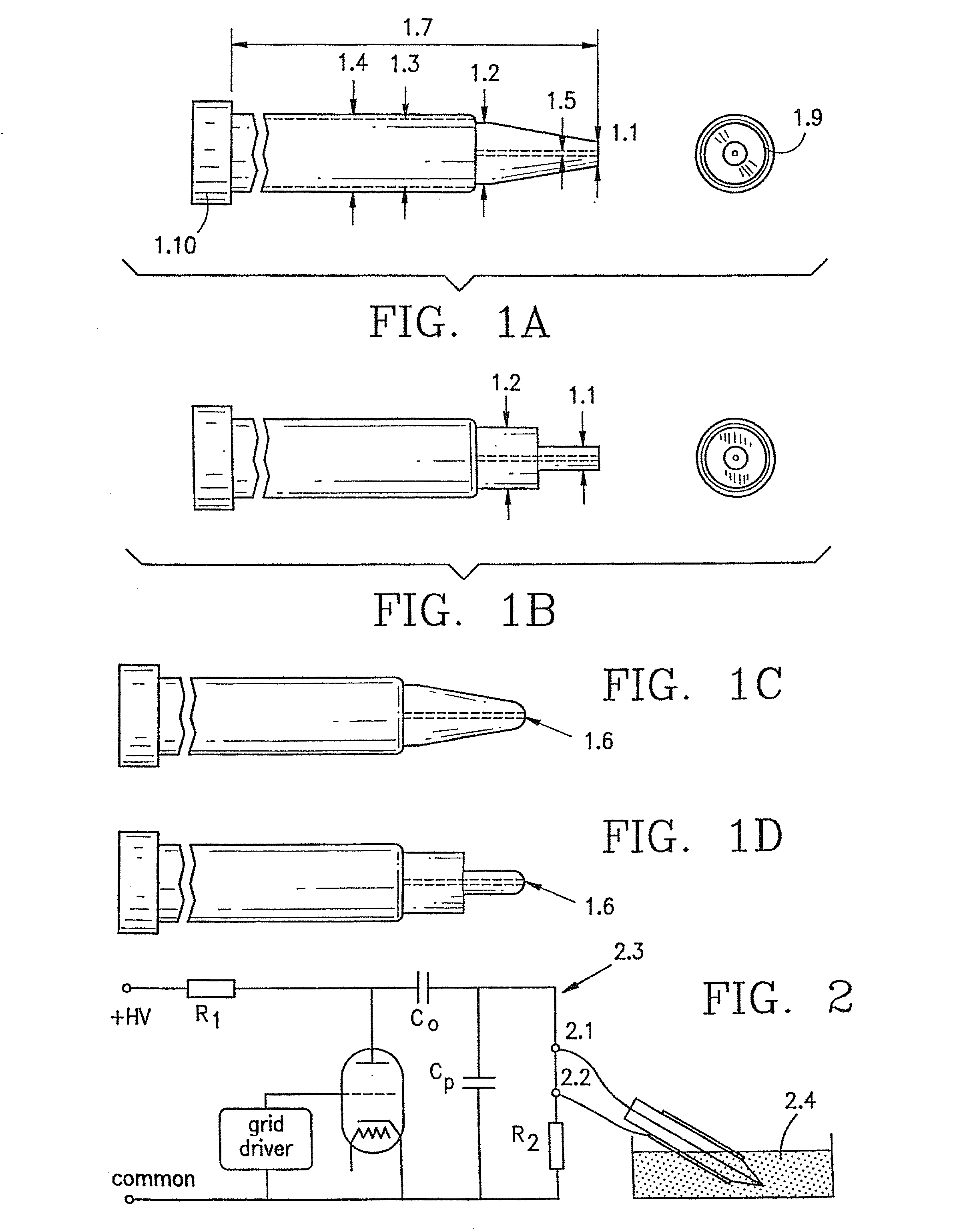
[0013] FIG. 1A is a schematic illustration of a microelectrode in accordance with the invention, utilizing a single wire and having a tapered insulator with a flat tip;

[0014] FIG. 1B is a schematic illustration of a microelectrode in accordance with the invention, utilizing a single wire and having a nontapered insulator with a flat tip;

[0015] FIG. 1C is a modification of the device of FIG. 1A, wherein the insulator has a rounded tip;

[0016] FIG. 1D is a modification of the device of FIG. 1B, wherein the insulator has a rounded tip;

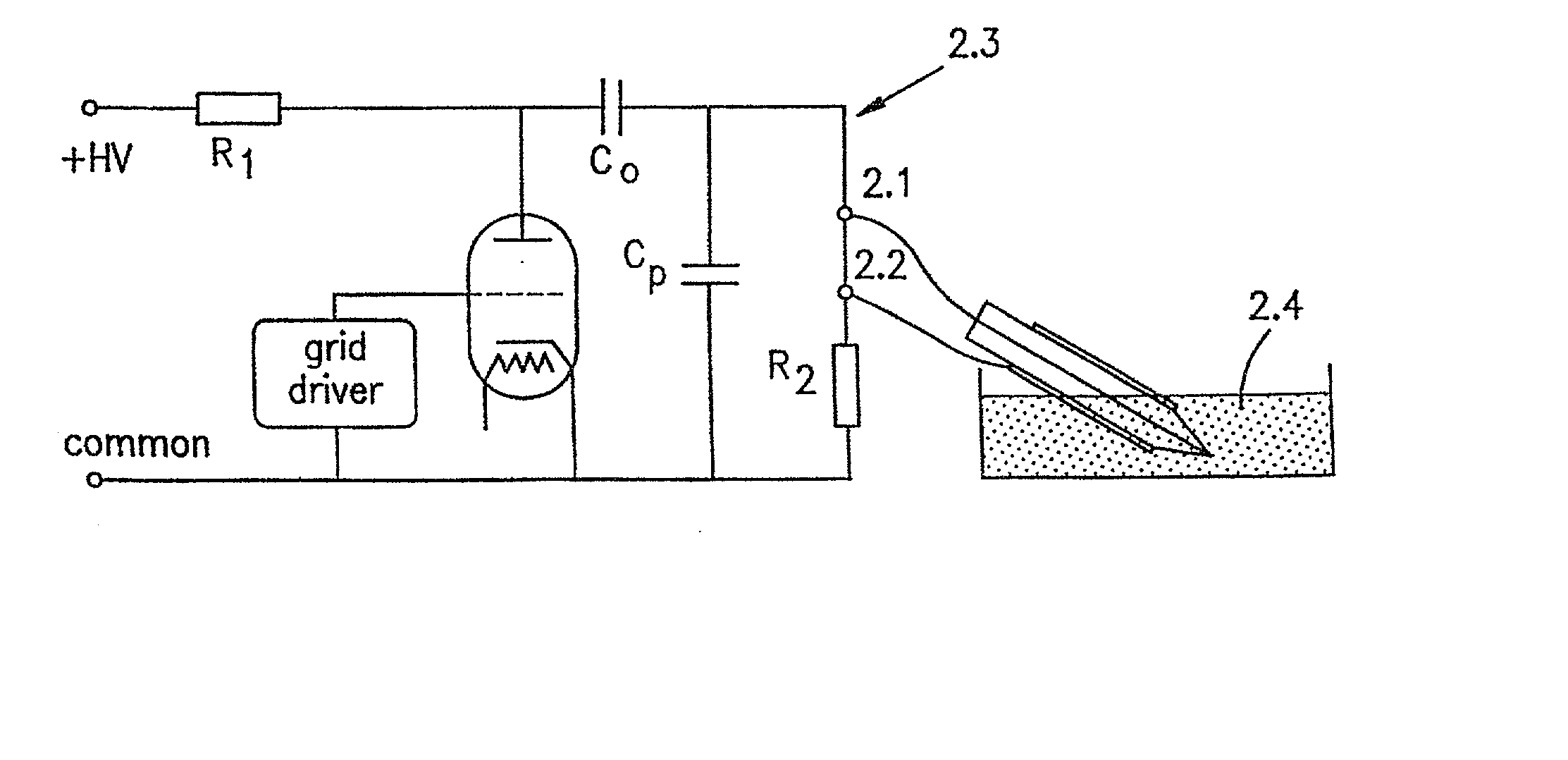
[0017] FIG. 2 is a schematic diagram of a high voltage generator connected to the microelectrode of FIGS. 1A-1D;

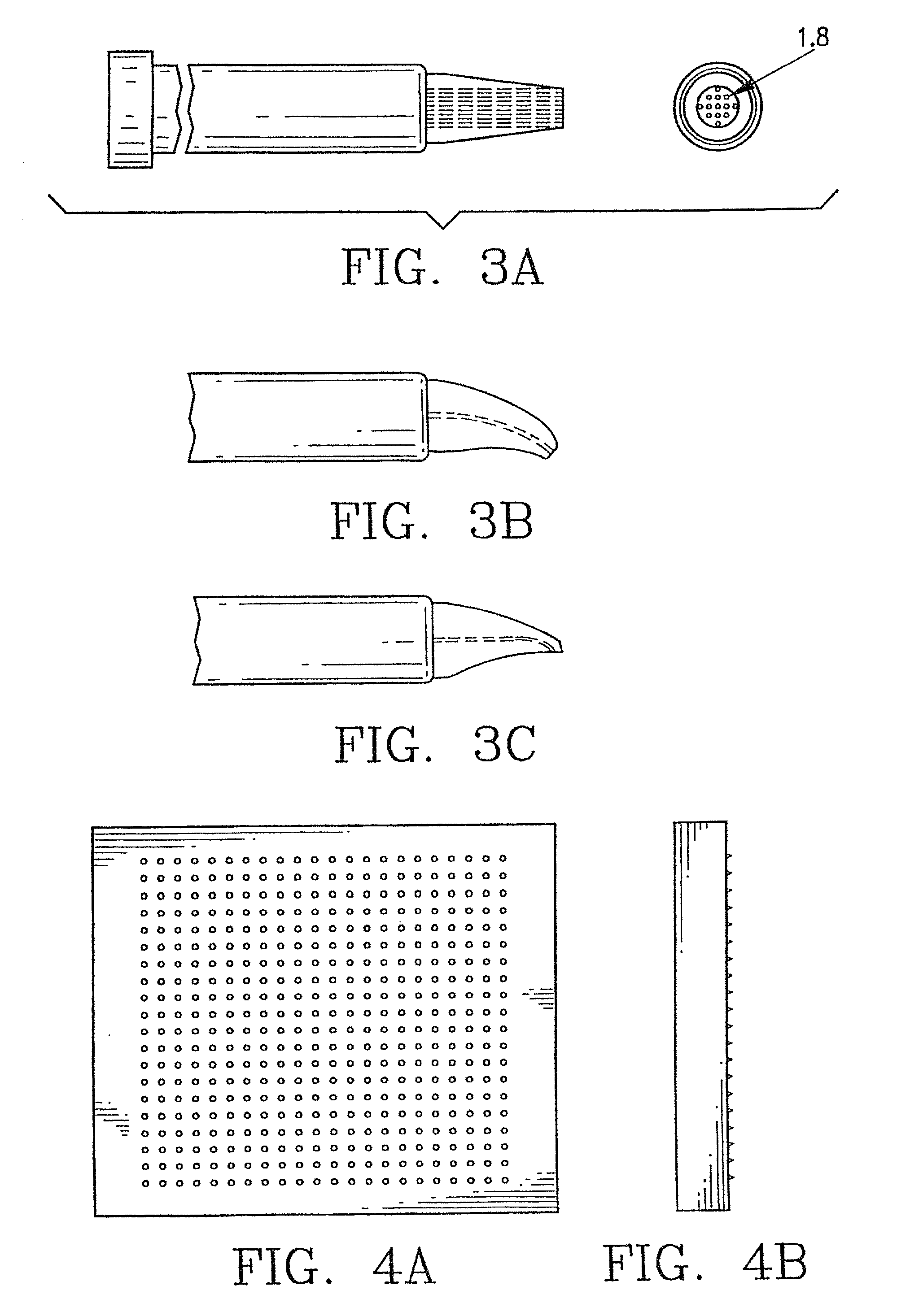
[0018] FIG. 3A is a schematic illustration of a microelectrode in accordance with the invention, having multiple wires;

[0019] FIG. 3B is a schematic illustration of a partially bent, single-wire microelectrode in accordance with the invention, ha...


PUM


Abstract

A method and device for electrical emulation of pulsed laser is disclosed. The device utilizes high voltage electrical discharges of sub-microsecond duration in a liquid medium to produce cavitation bubbles of sub-millimeter size for use in high speed precision cutting. Such bubbles are produced by a micro-electrode (1.6) having a central wire having a diameter of 1 microns to 100 microns embedded in an insulator. A coaxial electrode (1.9) surrounds the insulator, and may be spaced from the outer surface of insulator to provide a path for removing tissue.

Description

[0001] The invention is a method and a device that allows for the electrical emulation of the microsurgical abilities of pulsed lasers. These lasers are the basis for new laser procedures that are responsible for high speed and high precision cutting action in biological liquid environments with minimal damage to the surrounding mechanism. They work by producing cavitation bubbles. The action of these lasers and laser procedures are simulated in the current invention by using protocols that are a part of this invention. These protocols regulate the electrical current injected into the specialized device that has been devised. As a result it is possible to emulate the cavitation bubble formation cutting that has become a hallmark of various pulsed laser procedures. The invention allows the same device to be used for such an emulation of these cavitation bubbles while also allowing for heat induced coagulation and poration of biological materials.[0002] Various pulsed lasers have been...

Claims


Application Information

Patent Timeline
Patent Type & Authority Applications(United States)
IPC IPC(8): A61B17/00A61B17/22A61B18/14A61B18/26
CPCA61B18/14A61B18/1477A61B18/26A61B2017/00154A61B2017/22008Y10S977/856A61B2018/00601A61B2018/126A61B2018/1425A61B2018/1472A61B17/22022A61B2018/0016
Inventor LEWIS, AARONPALANKER, DANIEL V.TUROVETS, IGOR
Owner NANOPTICS
Learn More