Cache with DMA and dirty bits

a technology of dma and cache, applied in the field of microprocessors, can solve the problems of large main memory, significantly slower, and large cache siz

Inactive Publication Date: 2002-06-06
TEXAS INSTR INC
View PDF5 Cites 13 Cited by
  • Summary
  • Abstract
  • Description
  • Claims
  • Application Information

AI Technical Summary

Benefits of technology

0006] Particular and preferred aspects of the invention are set out in the accompanying independent and dependent claims. In accordance with a first aspect of the invention, there is provided a digital system having at least one processor, with an associated multi-segment cache memory circuit. Within the cache, a data array is arranged as a plurality of lines each having one or more segments. Each of the segments has a corresponding dirty bit within a set of dirty bits, each dirty bit is operable to indicate if the corresponding segment contains data that is not coherent with a secondary memory and is therefore referred to as "dirty."

Problems solved by technology

The main memory is generally much larger than the cache, but also significantly slower.

Method used


Image

  • Cache with DMA and dirty bits
  • Cache with DMA and dirty bits
  • Cache with DMA and dirty bits

Examples


Embodiment Construction

[0034] Although the invention finds particular application to Digital Signal Processors (DSPs), implemented, for example, in an Application Specific Integrated Circuit (ASIC), it also finds application to other forms of processors. An ASIC may contain one or more megacells which each include custom designed functional circuits combined with pre-designed functional circuits provided by a design library.

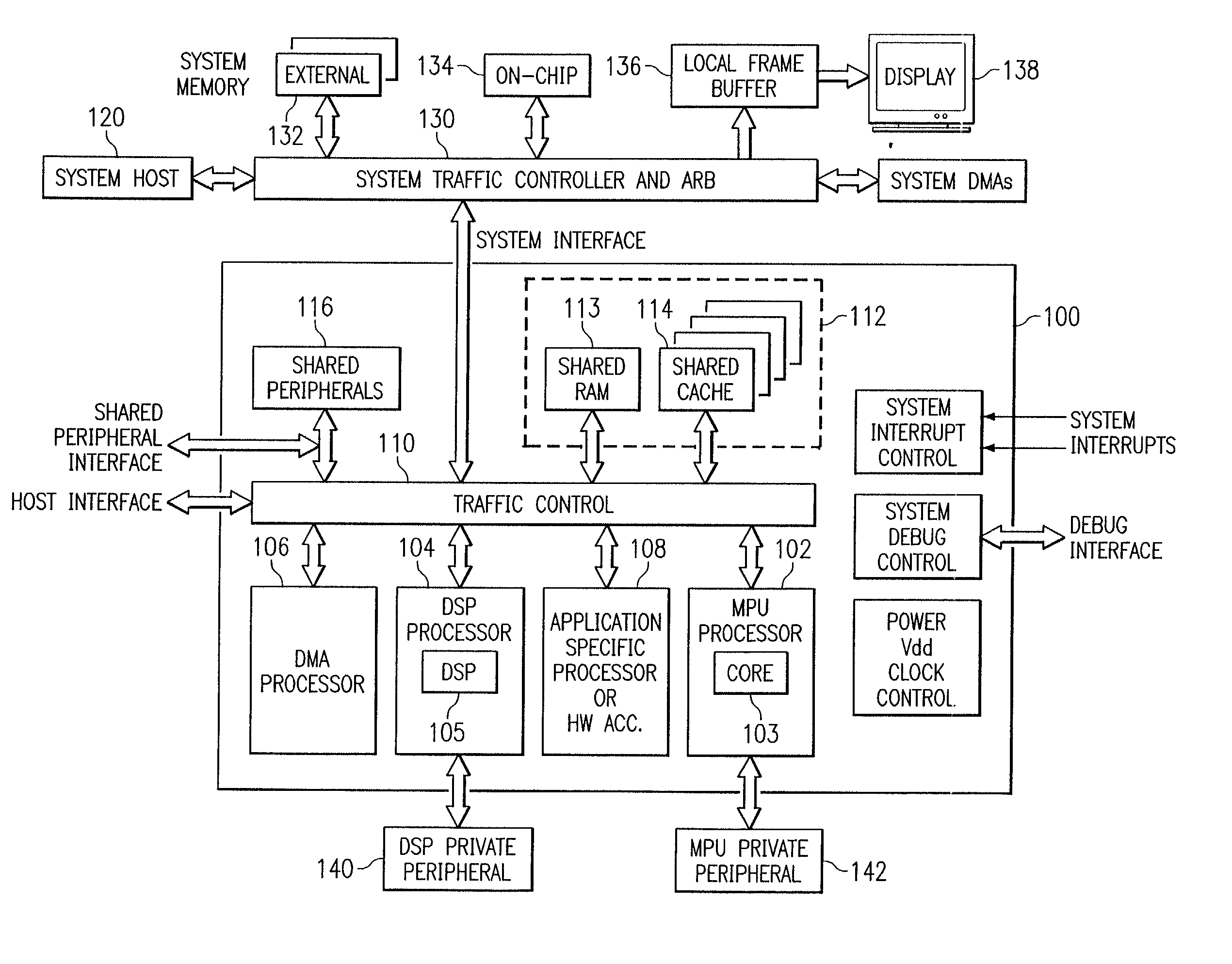
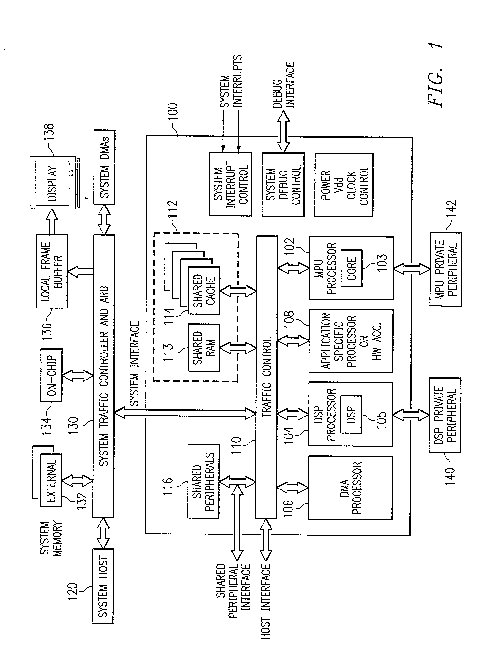
[0035] FIG. 1 is a block diagram of a digital system that includes an embodiment of the present invention in a megacell core 100 having multiple processor cores. In the interest of clarity, FIG. 1 only shows those portions of megacell 100 that are relevant to an understanding of an embodiment of the present invention. Details of general construction for DSPs are well known, and may be found readily elsewhere. For example, U.S. Pat. No. 5,072,418 issued to Frederick Boutaud, et al, describes a DSP in detail. U.S. Pat. No. 5,329,471 issued to Gary Swoboda, et al, describes in detail how ...


PUM


Abstract

A digital system and method of operation is provided in which the digital system has at least one processor, with an associated multi-segment cache memory circuit (506(n). Validity circuitry (VI) is connected to the memory circuit and is operable to indicate if each segment of the plurality of segments holds valid data. Dirty bit circuitry (DI) is connected to the memory circuit for indicating if data within the cache is incoherent with a secondary back-up memory. DMA circuitry can transfer (1652) blocks of data/instructions (1660) between the cache and a secondary memory (1602). A transfer mode circuit (1681) controls how DMA operations are affected by the dirty bits. If the transfer mode circuit is in a first mode, a DMA operation transfers only segments (1661) indicated as dirty (1685). If the transfer mode circuit is in a second mode, a DMA operation transfers and entire block of data (1660) without regard to dirty indicators (1686). DMA transfers from the cache to secondary memory are thereby configured to be responsive to the dirty bits. A dirty bit mode circuit (1680) controls how DMA transfers affect the dirty bits. When the mode circuit is in a first mode, DMA transfers set the affected dirty bits to a clean state. When the dirty bit mode circuitry is in an alternate mode, DMA transfers set the affected dirty bits to a dirty state. A cache clean operation will thus copy data provided by a DMA transfer and indicated as dirty into backup secondary memory.

Description

[0001] This application claims priority to European Application Serial No. 00402331.3, filed Aug. 21, 2000 (TI-31366EU) and to European Application Serial No. 01400686.0, filed Mar. 15, 2001 (TI-32242EU). U.S. patent application Ser. No. ______ (TI-31366US) is incorporated herein by reference.FIELD OF THE INVENTION[0002] This invention generally relates to microprocessors, and more specifically to improvements in cache memory and access circuits, systems, and methods of making.BACKGROUND[0003] Microprocessors are general purpose processors which provide high instruction throughputs in order to execute software running thereon, and can have a wide range of processing requirements depending on the particular software applications involved. A cache architecture is often used to increase the speed of retrieving information from a main memory. A cache memory is a high speed memory that is situated between the processing core of a processing device and the main memory. The main memory is ...

Claims


Application Information

Patent Timeline
Patent Type & Authority Applications(United States)
IPC IPC(8): G06F1/20G06F1/32G06F9/312G06F11/34G06F12/02G06F12/08G06F12/0804G06F12/0879G06F12/0891G06F12/10G06F12/1027G06F12/1081
CPCG06F1/206G06F1/3203G06F1/329G06F9/30043G06F12/0292G06F12/0804G06F12/0879G06F12/0891G06F12/1027G06F12/1081G06F2201/81G06F2201/885G06F2212/1028Y02B60/144Y02B60/1225Y02D10/00
Inventor CHAUVEL, GERARDLASSERRE, SERGE
Owner TEXAS INSTR INC
Why Eureka
Try Eureka