PWM motor drive apparatus with increase of low speed capability

a technology of high-phase order and motor drive, which is applied in the direction of motor/generator/converter stopper, electric motor speed/torque regulation, dynamo-electric converter control, etc., can solve the problems of power electronics capabilities, increase comes at a cost, and the current in each winding is limited to the maximum current rating of the inverter, so as to reduce the current requirement of the inverter, increase the low speed slot current, and reduce the torque limitation

Inactive Publication Date: 2002-06-20
BOREALIS TECH LTD
View PDF0 Cites 40 Cited by
  • Summary
  • Abstract
  • Description
  • Claims
  • Application Information

AI Technical Summary

Benefits of technology

[0009] The present invention increases the torque or speed capabilities of a high phase order motor drive system by increasing the utilization of the active switching elements while remaining within the voltage and current limitations of same. A range of harmonics is added to the inverter output waveform to increase the output voltage capacity of the inverter. Harmonics may also be used to adjust the current waveform feeding the motor, thereby increasing the current output capability of the inverter. In a preferred embodiment, the motor is wound with an increased number of series turns to translate the additional available voltage into additional available slot current. In an alternative embodiment, a inverter voltage waveform is synthesized, producing an increased current output.FIGURES
[0020] In another embodiment, the number of series turns in the phase winding set is increased above that associated with sinusoidal drive. In this case, the increased voltage capability of the inverter is matched by an increased voltage requirement of the motor. The base speed of the system remains the same; however, the current requirements of the motor operating in any given output state are reduced. This permits the use of power electronic switching elements with a lower current rating, or this permits the same power electronic switching elements to cause greater net slot current, resulting in greater mechanical output.
[0023] In a higher phase order machine, for example, in a thirty-phase machine, the results of adding harmonic components is rather different. In a high phase order machine, these harmonics will actually flow in the windings. This is even the case when 
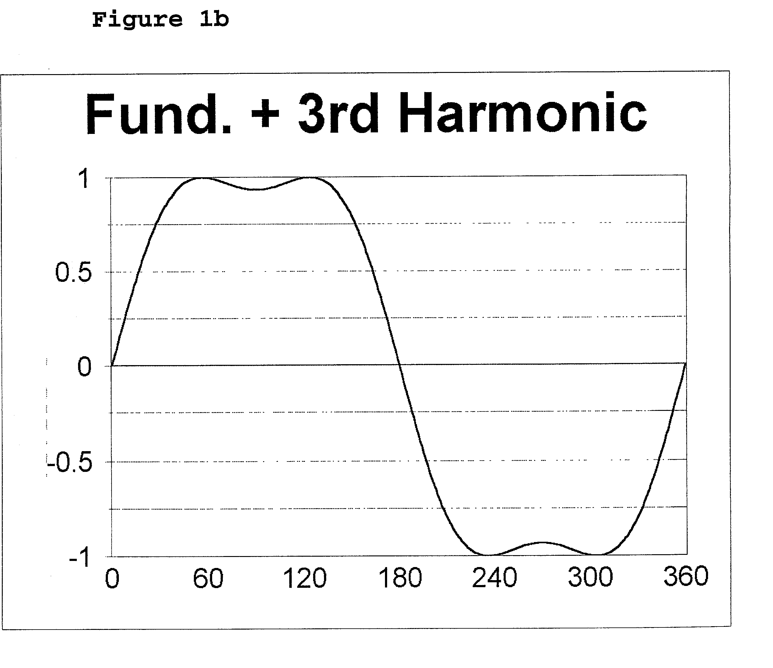
third harmonic components are part of the synthesized inverter output. However, in stark contrast to the three phase machines, these harmonic current flows do not greatly harm efficiency, and in fact beneficially produce torque. In a high phase order machine, all 
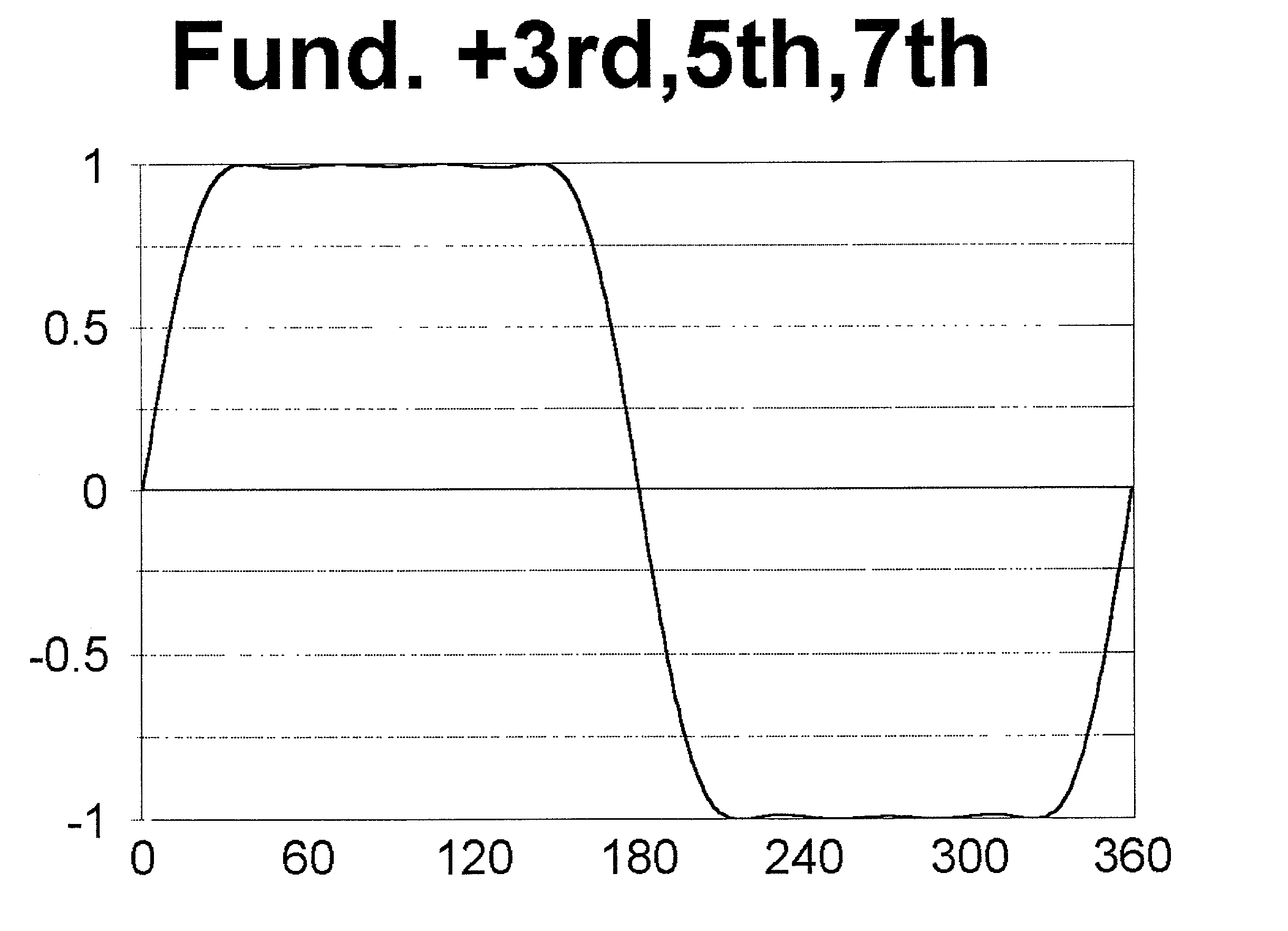
harmonics up to the phase count may be beneficially used to produce torque; thus the RMS content of the waveform may be increased by adding a plurality of odd-order harmonics. When added in correct ratios, these harmonics will also increase the fundamental voltage impressed upon the terminals of the motor.
[0024] The basic technique of changing the waveshape of a limiting current flow in order to increase the ratio of RMS value to peak value may also be used during low speed operation. When the motor is operated at low speed, the terminal voltage requirements are greatly reduced, but current requirements remain high. A voltage waveform may be synthesized by the inverter with suitable voltage waveshape so as to cause current to flow in the motor windings, the current waveform having a high ratio of RMS current to peak amplitude current. For a given peak inverter current, this increases the RMS current, and thus the torque available from the motor. Because of the necessary voltage waveform, the RMS versus peak voltage ratio may be harmed; however, for low speed operation this reduction in voltage capability is not a problem, as the motor terminal voltage will be well below inverter capabilities at low motor speed. The change in current waveform will increase the available overload torque during periods when such a waveform is synthesized, whilst allowing for a normal motor operational envelope at all other times.
[0027] As noted above, the ability to increase the inverter voltage RMS output capability may be used either to increase the base speed of the motor by providing sufficient voltage to operate at higher speed, or, by increasing the number of series turns, it may be used to increase the output torque capabilities of the motor drive system. The ability to increase the ratio of current RMS value to current peak value be used to increase the torque available from the motor drive system by directly increasing slot current. Through the expedient of reducing the number of series turns, this increase in inverter output capability may be used to increase the motor base speed while maintaining the same low speed torque capabilities.
[0028] The range of these various embodiments may be summarized as follows: changing the voltage waveform to increase the voltage RMS output increases the voltage which the inverter may supply to the motor. Changing the voltage waveform to increase the current RMS output increases the current which the inverter may supply to the motor. These changes in output capability have well known effects upon motor capability, and may be utilized either with the number of series turns calculated for sinusoidal drive, or the number of series turns may be adjusted to accommodate the increase in voltage or current. These changes in inverter output capability may also be advantageously used by reducing the size and cost of the inverter, through a reduction in voltage or current requirements of the power switching elements needed to provide a given motor mechanical output capability.

Problems solved by technology

A further limiting factor is power electronics capabilities which provide the electrical drive to the motor.
The current in each of the windings is however limited to inverter maximum current ratings.
However, this increase comes at a cost; the increased number of series turns raises the voltage of the winding, and increases the voltage required to feed the current into the winding.
However, this increased voltage requirement will decrease the maximum speed at which the inverter can supply sufficient voltage to the motor.
Voltage too is limited to inverter ratings.

Method used


Image

  • PWM motor drive apparatus with increase of low speed capability
  • PWM motor drive apparatus with increase of low speed capability
  • PWM motor drive apparatus with increase of low speed capability

Examples


Embodiment Construction

[0030] In a preferred embodiment, a high phase order induction motor is supplied with electrical power by a high phase order inverter. This high phase order inverter is provided with control means capable of adjusting the output waveform synthesized by the output power switching elements of the inverter. The synthesized waveform consists of the sum of the fundamental component and the harmonic components, in controlled proportion.

[0031] As is well known, the output voltage of the inverter must be adjusted in response to different motor operational states.

[0032] When possible, the synthesized waveform consists of essentially pure sinusoidal, or fundamental, output. However, when sinusoidal drive would result in a peak voltage amplitude which is greater than the maximum inverter output voltage, harmonic components are added to the synthesized waveform in order to reduce the peak amplitude of the synthesized waveform. As the desired output voltage is increased, additional harmonic comp...


PUM


Abstract

Maximizing current from a given power inverter in an electrical rotating machine and maintaining the speed of an electrical rotating machine which has more turns of the winding.

Description

[0001] The structure of a dynamo electric machine plays an important role in the limits to the mechanical capacity of the machine. A further limiting factor is power electronics capabilities which provide the electrical drive to the motor.[0002] Electric motors are often operated with electronic variable speed drive systems, which adjust the voltage and current being supplied to the motor in order to operate the motor at a desired speed under a given torque load, or to control the torque load to a fixed value, or to otherwise control the mechanical output of the motor. A particularly useful type of variable speed drive is the polyphase alternating current inverter, which may be used to operate polyphase AC motors.[0003] In many applications, a fixed amount of input electrical power is available, and this is to be converted to mechanical output power as needed. It is desirable that the full available electrical power be available for conversion to mechanical power over a wide speed r...

Claims


Application Information

Patent Timeline
Patent Type & Authority Applications(United States)
IPC IPC(8): H02P27/02
CPCH02P27/02
Inventor EDELSON, JONATHAN SIDNEY
Owner BOREALIS TECH LTD
Why Eureka
Try Eureka