
Method and apparatus for the calibration and compensation of sensors

a low-pressure sensor and calibration method technology, applied in the field of sensors, can solve problems such as error compensation to achieve accurate measurements, errors in pressure readings, and costly and time-consuming processes

Inactive Publication Date: 2002-06-27
HONEYWELL INT INC
View PDF0 Cites 29 Cited by
  • Summary
  • Abstract
  • Description
  • Claims
  • Application Information

AI Technical Summary

Problems solved by technology

Such pressure transducers may be sensitive to various disturbances, such as temperature changes, which, if uncompensated, will cause errors in the pressure reading.
Error compensation to achieve accurate measurements, however, can be a costly and time-consuming process.
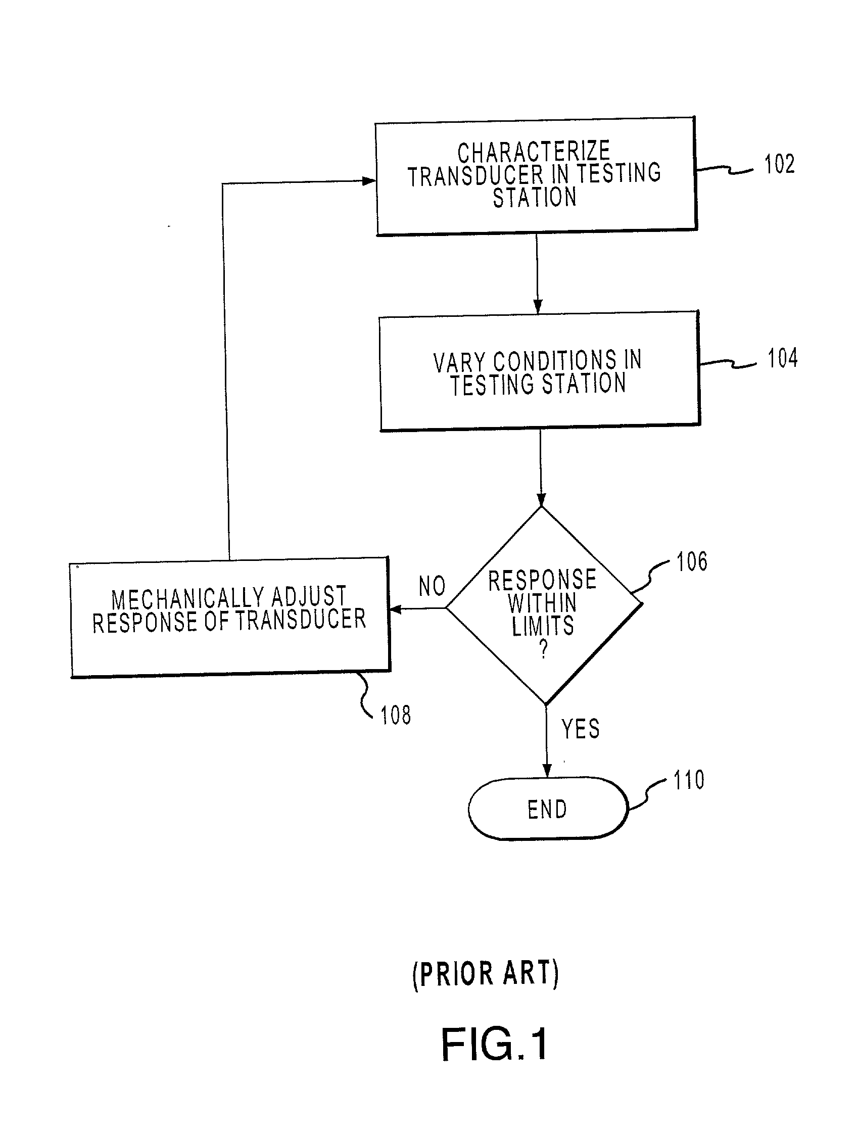
The process is time consuming, as the transducer may have to be calibrated and re-calibrated several times to calibrate the sensor.
In addition the calibration process may not be as precise as desired.
However, that degree of precision may not be possible because the mere measuring of the resistance may cause the resistance to change.
However, such a transducer may still suffer from various errors.
While a transducer such as that described in the '978 patent may adequately compensate for certain mechanical noise issues and gravity issues, such a transducer does not adequately address all of the issues respecting the calibration of the sensor.

Method used


Image

  • Method and apparatus for the calibration and compensation of sensors
  • Method and apparatus for the calibration and compensation of sensors
  • Method and apparatus for the calibration and compensation of sensors

Examples


Embodiment Construction

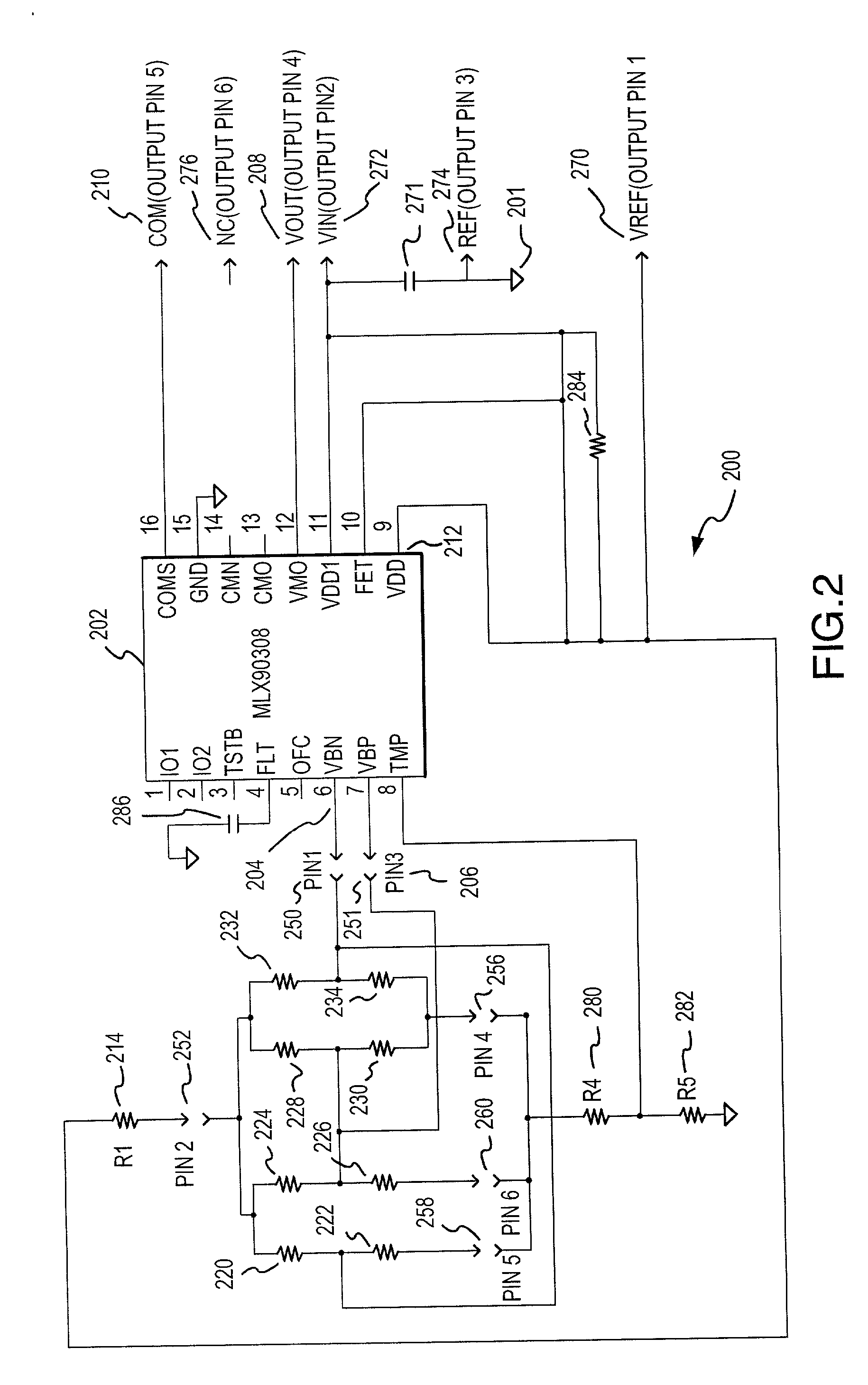
[0022] The present invention may be described herein in terms of various functional components and various processing steps. It should be appreciated that such functional components may be realized by any number of hardware or structural components configured to perform the specified functions. For example, the present invention may employ various integrated components comprised of various electrical devices, e.g., resistors, transistors, capacitors, diodes and the like, whose values may be suitably configured for various intended purposes. In addition, the present invention may be practiced in any integrated circuit application where a calibration is desired. Such general applications that may be appreciated by those skilled in the art in light of the present disclosure are not described in detail herein. However for purposes of illustration only, exemplary embodiments of the present invention will be described herein in connection with pressure sensors. Further, it should be noted...


PUM


Abstract

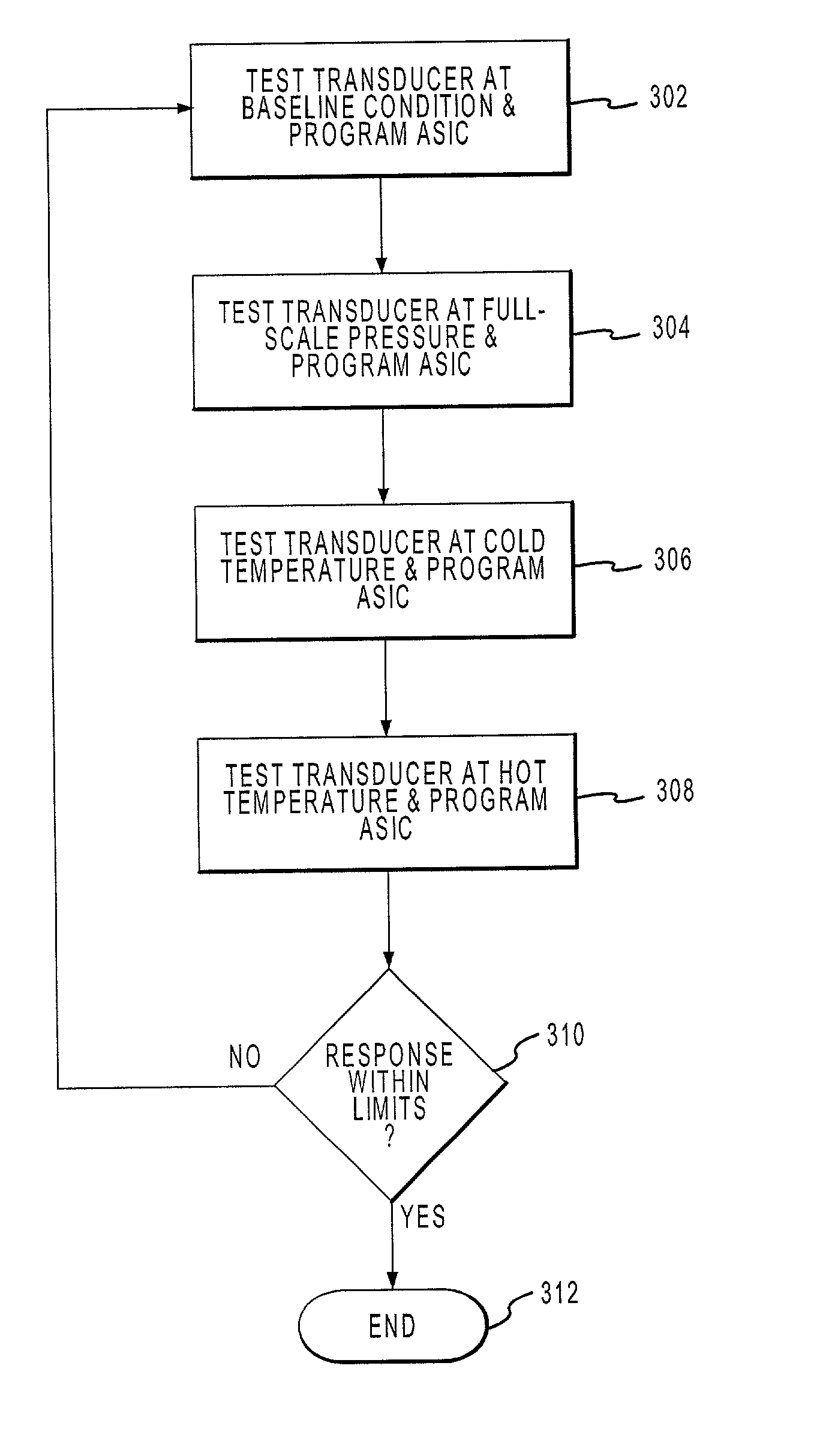
The present invention discloses a method of using of a programmable circuit to calibrate a transducer. The programmable circuit is coupled to or communicates with a computer and to a testing station. The computer automatically varies the conditions of the testing station and programs the programmable circuit to produce a desired response. In another embodiment, a system is presented that can be used to measure various parameters that includes a programmable that may be mounted in the same package as a sensor. Such a system may include pressure sensors that are optimized to measure very low pressures.

Description

[0001] 1. Technical Field of the Invention[0002] The present invention relates generally to sensing equipment and more particularly to an apparatus and a method of calibrating low pressure sensors.[0003] 2. Description of Related Art[0004] Pressure transducers which use strain gauges in a Wheatstone Bridge configuration are well known in the art. Such pressure transducers may be configured to produce an output voltage or output current that is proportional to the pressure being sensed. The transducers will also typically have a specific range where the transducer can be used. For example, a transducer will have a rated cold temperature and a rated hot temperature and the transducer will be tested to ensure that it works properly within the rated temperature range. A similar situation occurs with respect to pressures, as a transducer will be rated and tested to function within a certain range of pressure.[0005] Such pressure transducers may be sensitive to various disturbances, such ...

Claims


Application Information

Patent Timeline
IPC IPC(8): G01D3/028G01L27/00G01D18/00
CPCG01D18/008
Inventor BENTLEY, IAN N.
Owner HONEYWELL INT INC
Learn More