Vapor driven aerosol generator and method of use thereof
a generator and aerosol technology, applied in the field of aerosol generators, can solve the problems of inability to deliver material at such high flow rates, most known aerosol generators are incapable of generating aerosols having an average mass median particle diameter less than 2 microns, and the effect of reducing the number of aerosol generators
- Summary
- Abstract
- Description
- Claims
- Application Information
AI Technical Summary
Problems solved by technology
Method used
Image
Examples
first embodiment
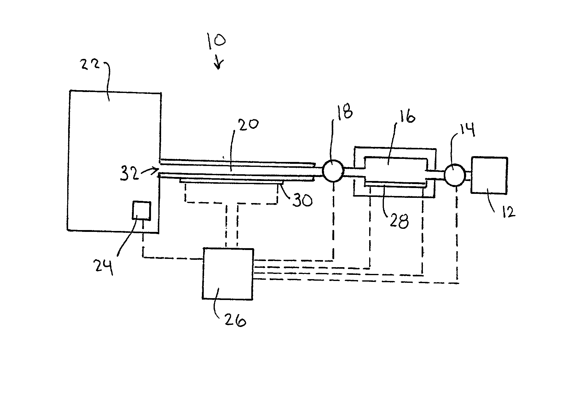
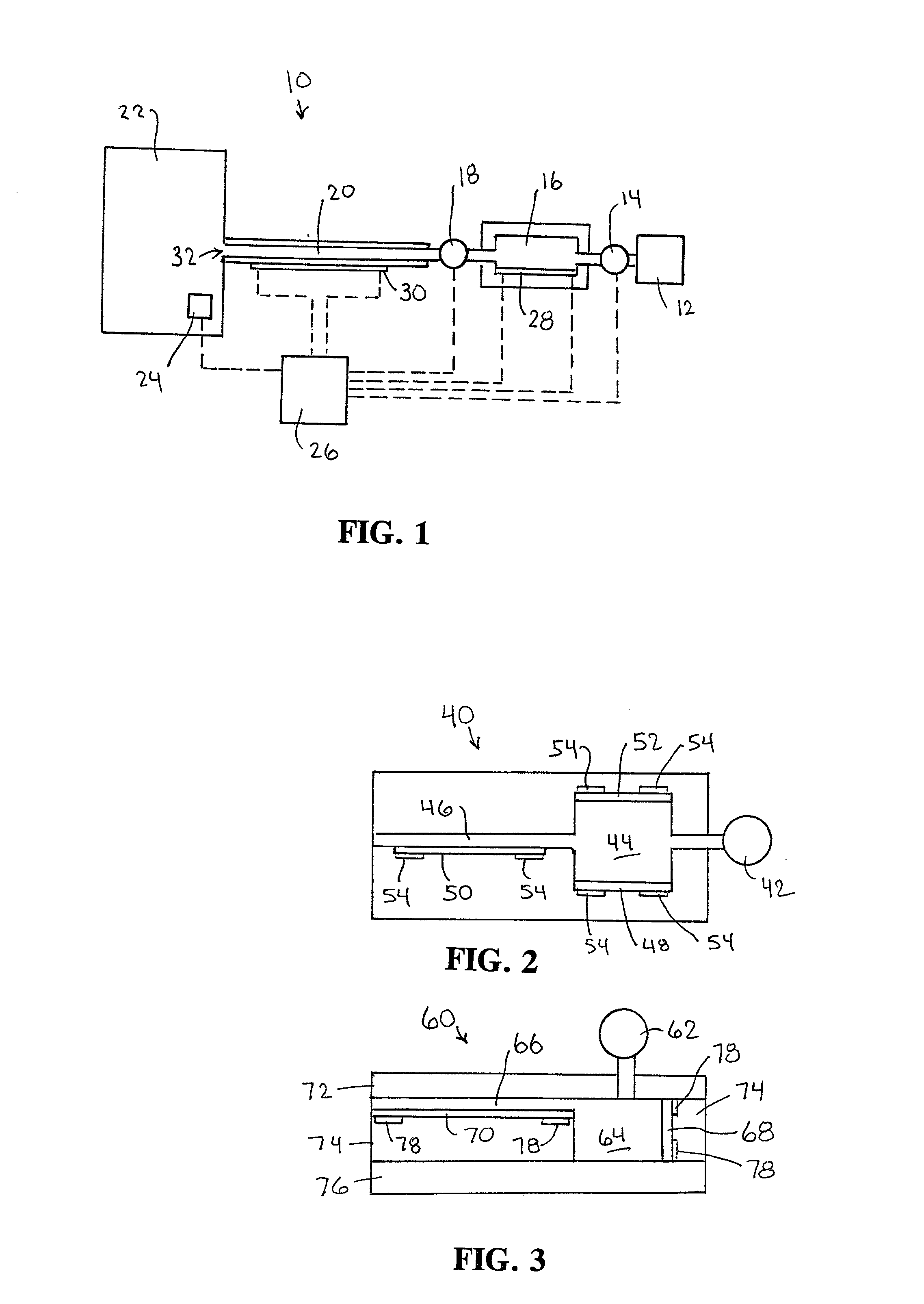
[0018] FIG. 2 shows a top cut-away view of a vapor driven aerosol generator 40 in accordance with another embodiment of the invention. As shown, the aerosol generator 40 includes a fluid supply 42, a chamber 44, a passage 46, a preheater 48 and a main heater 50. The preheater 48 can be arranged on one side of the chamber 44 such that fluid in the chamber 44 is heated to form a vapor bubble which expands and drives the remaining fluid in the chamber 44 into the passage 46. If desired, an additional preheater 52 can be provided in the chamber 44 in order to provide additional heating of the fluid. The heaters 48, 52 extend horizontally along bottom and top walls of the chamber 44. The heaters 48, 50, 52 are preferably thin films of resistance heating material. In order to pass electrical current through the heaters, the heaters can be in electrical contact with suitable electrical contacts 54. A suitable power source such as a battery can be used to deliver sufficient direct current t...
third embodiment
[0020] FIG. 3 shows a side view of a vapor driven aerosol generator in accordance with the invention. As shown, the aerosol generator 60 includes a fluid supply 62, a chamber 64, a passage 66, a preheater 68 and a main heater 70. The aerosol generator 60 can be formed from solid state components such as layers 72, 74, 76 of metal, organic or ceramic material such as a polymer material or ceramic material. If desired, layers 74 and 76 can comprise a single layer which has been machined or etched to form the passage 66 and the chamber 64. Alternatively, one or more layers can be interposed between the layers 74 and 76 so as to form the passage 66 and the chamber 64. As in the case of the embodiment shown in FIG. 2, the heaters 68, 70 can be supplied power by contacts 78. The heater 68 is arranged to extend vertically along an inner sidewall of the chamber 64. In arrangements wherein the heater contacts the fluid, it is desirable to coat the heater with a material which is non-reactive...
PUM
 Abstract
Description
Claims
Application Information
 - R&D
- Intellectual Property
- Life Sciences
- Materials
- Tech Scout
- Unparalleled Data Quality
- Higher Quality Content
- 60% Fewer Hallucinations
Browse by: Latest US Patents, China's latest patents, Technical Efficacy Thesaurus, Application Domain, Technology Topic, Popular Technical Reports.
© 2025 PatSnap. All rights reserved.Legal|Privacy policy|Modern Slavery Act Transparency Statement|Sitemap|About US| Contact US: help@patsnap.com


