Emergency lighting remote monitoring and control system

a technology for remote monitoring and control systems, applied in testing/monitoring control systems, process and machine control, instruments, etc., can solve the problems of affecting the operation of the equipment, the cost of personnel to perform the testing and recording of the test results, and the inability to monitor the lighting. the effect of reducing the operating cost and reducing the installation cos

Inactive Publication Date: 2002-06-27
IOTA ENG
View PDF0 Cites 190 Cited by
  • Summary
  • Abstract
  • Description
  • Claims
  • Application Information

AI Technical Summary

Benefits of technology

0027] Advantages of the invention include reduced operating costs, reliable scheduling of tests, reliable recording of test results, quick diag

Problems solved by technology

There are several problems with the prior art.
One problem is that safety codes typically require a brief (i.e., 30 seconds) test be performed every month and a longer (i.e., 90 minutes) test be performed each year.
This is a large problem in a building which has many emergency lighting units.
Consequently, testing is easily neglected, records of the tests are easily lost, and costs for personnel to perform the testing a

Method used


Image

  • Emergency lighting remote monitoring and control system
  • Emergency lighting remote monitoring and control system
  • Emergency lighting remote monitoring and control system

Examples


Embodiment Construction

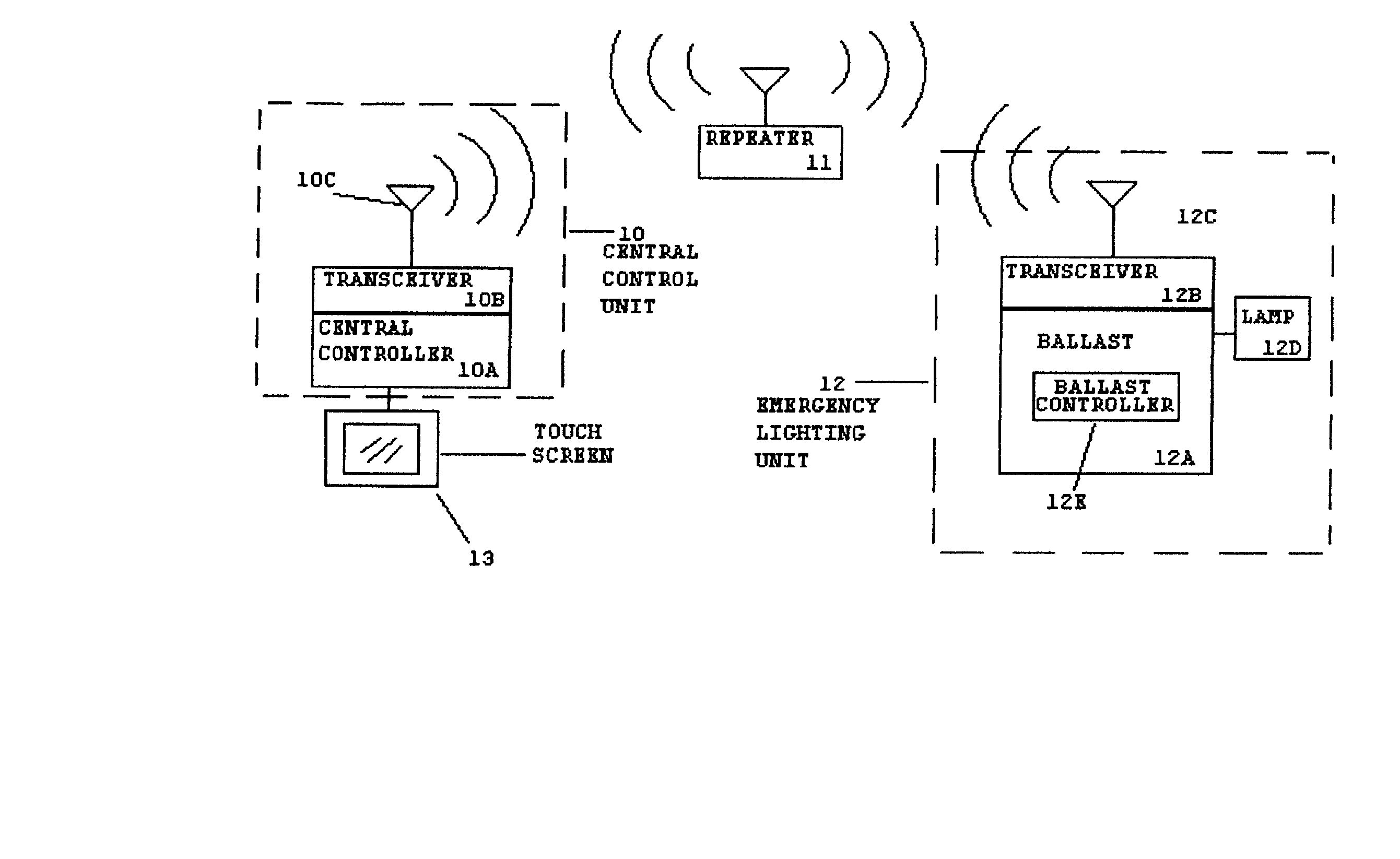
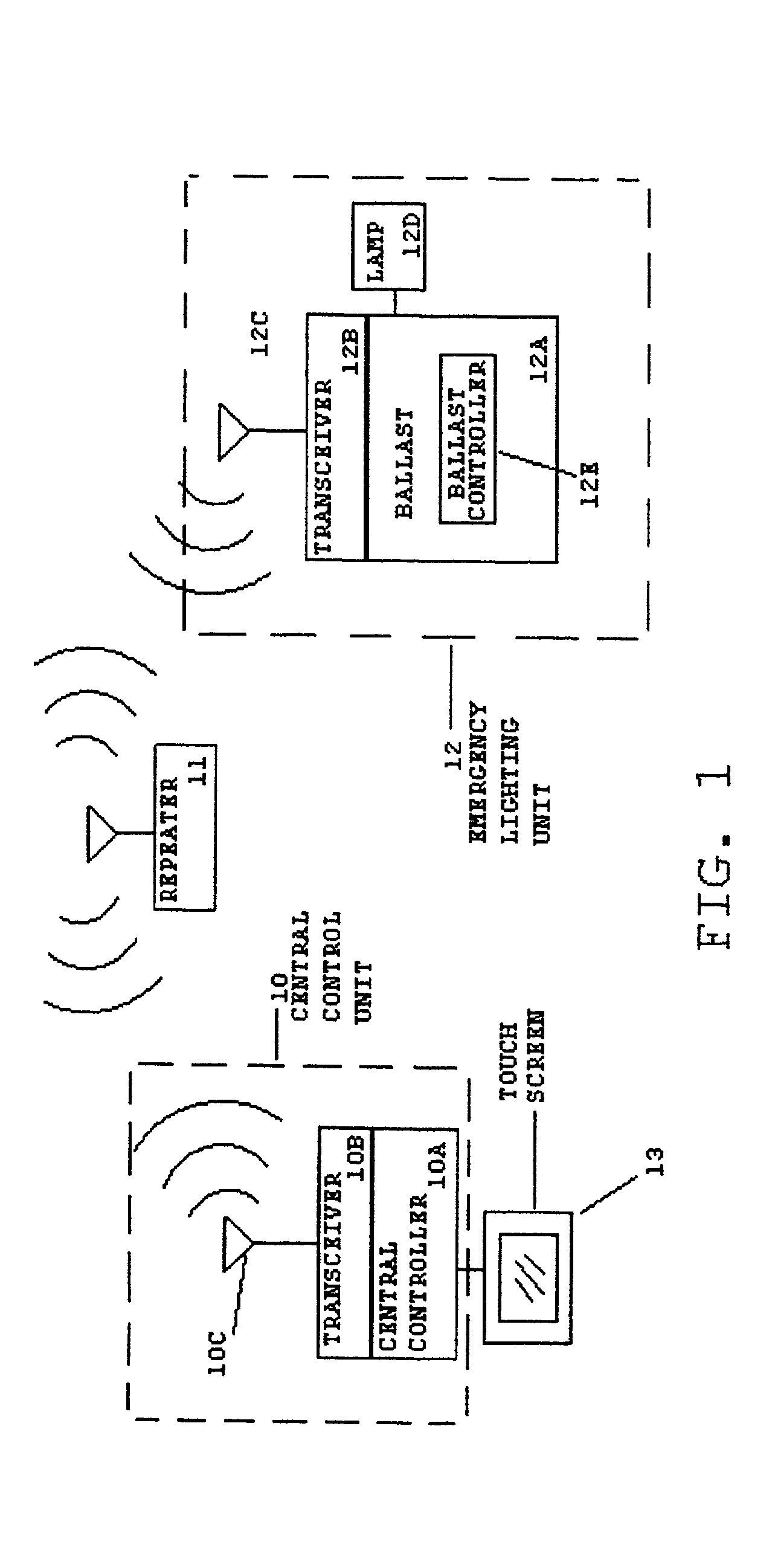
[0033] FIG. 1 is a block diagram of the preferred embodiment of the invention. Shown in FIG. 1 are central control unit 10, repeater 11, emergency lighting unit 12, and user interface 13. Central control unit 10 communicates with emergency lighting unit 12 via wireless radio signals. Repeater 11 relays signals between control unit 10 and lighting unit 12 when distance or interference prevents direct communication.

[0034] Emergency lighting unit 12 comprises ballast 12A, ballast transceiver 12B, ballast antenna 12C, and lamp 12D. Lighting unit 12 differs from the prior art in several aspects. Lighting unit 12 includes the addition of ballast transceiver 12B, antenna 12C, and ballast controller 12E. Ballast transceiver 12B and antenna 12C provide remote communication with control unit 10. Ballast controller 12E interfaces with transceiver 12B and coordinates self testing of emergency lighting unit 12. There may be up to 500 lighting units 12 located throughout a building or facility. A...


PUM


Abstract

An emergency lighting monitoring and control system controls and monitors the emergency lights in a building. A central control unit automatically schedules self tests for each of the emergency lights and stores the results of the tests in memory. The self tests include tests of the backup power source and the lamp. Some failures are predicted prior to actual failure. Failures are diagnosed and repairs are suggested. Light output is automatically monitored and adjusted. The central control unit generates a report of the self tests and notifies an operator of failures. An operator views test reports, controls the emergency lights, and schedules tests. The system automatically detects newly installed emergency lighting units.

Description

[0001] 1. Field of the Invention[0002] This invention is related in general to the field of emergency lighting and, in particular, to remote control and monitoring of emergency lights.[0003] 2. Description of the Related Art[0004] Emergency lighting is required by most safety codes in the United States. Emergency lights provide temporary lighting in the event of a power failure. During normal operation, power is provided from power mains to operate the lamp and to charge a backup power source (e.g., a battery). When power from the mains is interrupted, the backup power source provides power to the lamp for a limited time (typically 90 minutes).[0005] It is desirable to test emergency lights periodically to ensure proper operation. A typical prior art self test is initiated by a person pushing a button or flipping a switch on the lighting unit. Simple voltage and / or current tests are performed and a light or buzzer is activated if a test fails.[0006] There are several problems with t...

Claims


Application Information

Patent Timeline
IPC IPC(8): G08B5/36G08B7/06G08B29/12
CPCG08B7/062H05B37/0272G08B29/126H05B47/22H05B47/19
Inventor CONLEY, WILLIAM H. III
Owner IOTA ENG
Why Eureka
Try Eureka