Computer vision-based wireless pointing system

a wireless pointing and computer vision technology, applied in the field of wireless pointing systems, can solve the problems of reducing accuracy of rotational devices, affecting the accuracy of gyroscopic devices, and limiting the specific wavelength selected for transmission and detection,

Inactive Publication Date: 2002-07-04
KONINKLIJKE PHILIPS ELECTRONICS NV
View PDF12 Cites 251 Cited by
  • Summary
  • Abstract
  • Description
  • Claims
  • Application Information

AI Technical Summary

Benefits of technology

0017] Still further, additional functions can be added to the hand-held device to incorporate standard mouse and other control features therein, thus enabling the invention to function as a more full-functioned pointing device.

Problems solved by technology

The problem with these pointing devices is that they rely on the rotation of the device rather than translation.
Rotational devices decrease accuracy, and the devices are relatively heavy, as they require the mass to exploit the principle of momentum conservation.
These devices, though much lighter and less expensive than their gyroscopic counterparts, are limited to the particular wavelength selected for transmission and detection.
This wavelength-matching design constraint reduces the compatibility of the receiver to transmitters of a single wavelength, among other things.
CCD sensors are more accurate, but costly compared to CMOS sensors, which forgo accuracy for a substantial cost reduction.

Method used


Image

  • Computer vision-based wireless pointing system
  • Computer vision-based wireless pointing system
  • Computer vision-based wireless pointing system

Examples


Embodiment Construction

[0024] Preferred embodiments of the present invention will be described herein below with reference to the accompanying drawings. In the following description, well-known functions or constructions are not described in detail since they would obscure the invention in unnecessary detail.

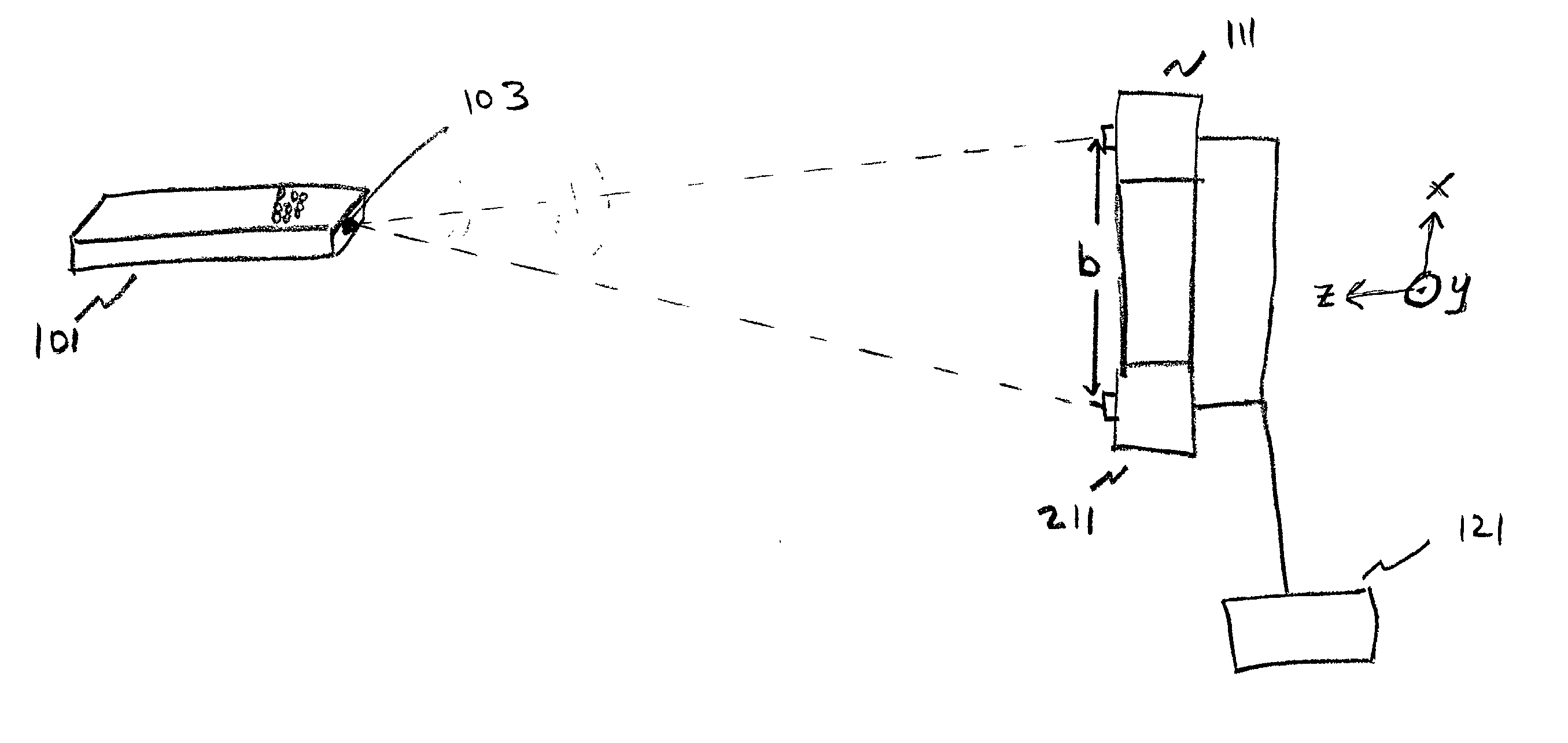
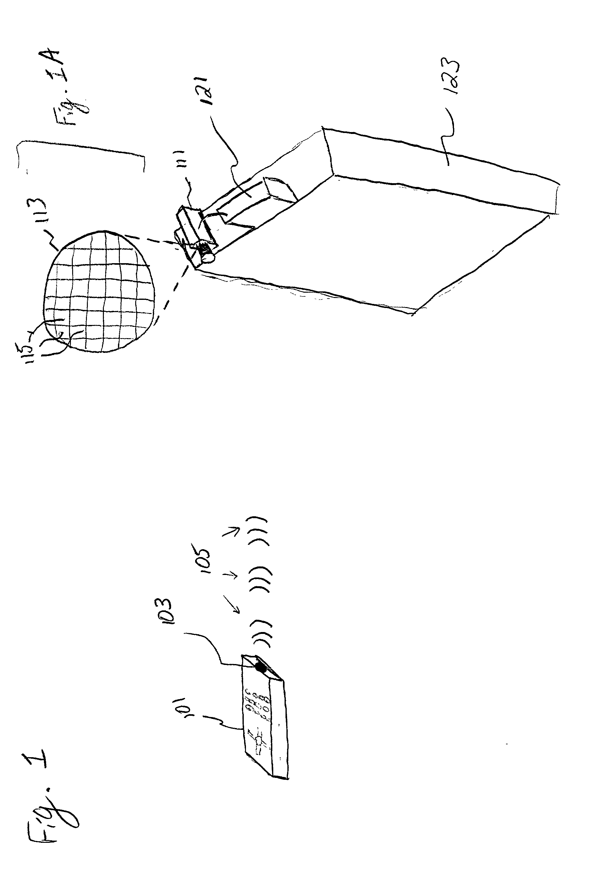
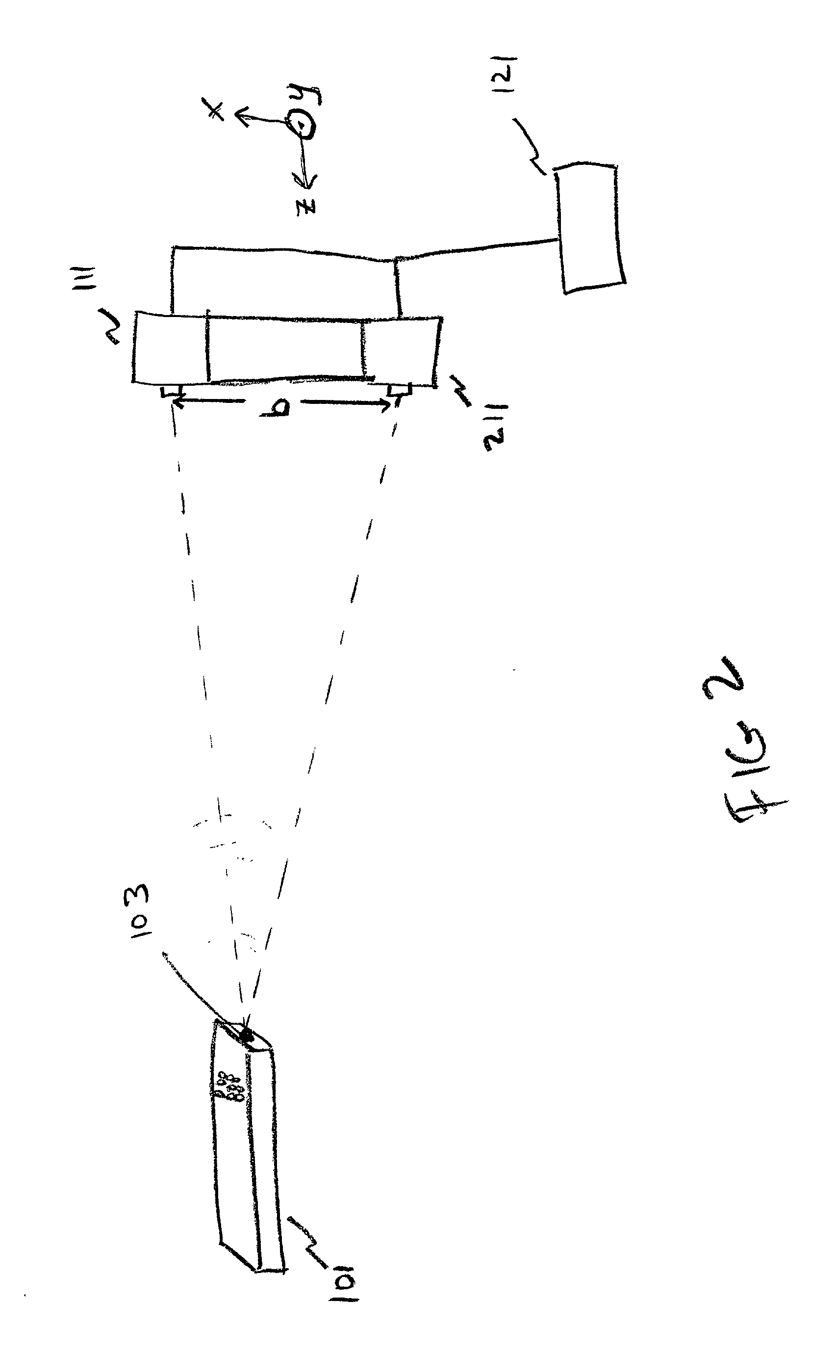
[0025] FIG. 1 is a representative view of a system according to an embodiment of the present invention. As shown in FIG. 1, hand-held device 101 is depicted as a standard remote control typically associated with a VCR or television. Incorporated into the hand-held device 101 is a control unit that causes an LED 103 to flash at a preset frequency. The starting of the flashing can be controlled by any switching method, for example, an on / off switch, a motion switch, or the device can be sensitive to user contact and the LED 103 can turn on when the user touches or picks up the device. Any other on / off method can be used, and the examples described herein are not meant to be restrictive.

[0026] After the ...


PUM


Abstract

A system comprising at least one light source in a movable hand-held device, at least one light detector that detects light from said light source, and a control unit that receives data from the at least one light detector. The control unit determines the position of the hand-held device in at least two-dimensions from the data from the at least one light detector and translates the position to control a feature on a display.

Description

[0001] 1. Field of the Invention[0002] The present invention relates to a wireless pointing system, and more particularly to a wireless pointing system that determines the location of a pointing device and maps the location into a computer to display a cursor or control a computer program.[0003] 2. Description of the Related Art[0004] Pointing devices such as a computer mouse or light pen are common in the computer world. These devices not only assist a user in the operation of a computer, but are also at a stage in their development to free the user from needing an interface that is hardwired to the computer. One type of wireless device now available, for example a wireless mouse, utilizes a gyroscopic effect to determine the position of the pointing device. This information is converted into digital positional data and output onto a display as, for example, a cursor. The problem with these pointing devices is that they rely on the rotation of the device rather than translation. Ro...

Claims


Application Information

Patent Timeline
Patent Type & Authority Applications(United States)
IPC IPC(8): G06F3/033G06F3/0346G06F3/038G06F3/042H04N5/225H04N101/00
CPCG06F3/0304G06F3/0325G06F3/0346
Inventor COLMENAREZ, ANTONIO J.COHEN-SOLAL, ERICWEINSHALL, DAPHNALEE, MI-SUEN
Owner KONINKLIJKE PHILIPS ELECTRONICS NV
Why Eureka
Try Eureka