Hybrid fuel cell reactant flow fields

a fuel cell and reactant technology, applied in the direction of fuel cells, fuel cell details, electrochemical generators, etc., can solve the problems of parasitic power, consuming a greater proportion of the electricity generated by the fuel cell, and unable to achieve effective force convection, etc., to achieve the effect of increasing pressur

Inactive Publication Date: 2002-07-04
AUDI AG
View PDF0 Cites 35 Cited by
  • Summary
  • Abstract
  • Description
  • Claims
  • Application Information

AI Technical Summary

Benefits of technology

0004] Objects of the invention include provision of fuel cells which take advantage of the reactant utilization obtainable with

Problems solved by technology

However, the forced convection cannot be achieved effectively without an increase in the pressure drop across the flow field.
The increased pressure drop, in turn, requires

Method used


Image

  • Hybrid fuel cell reactant flow fields
  • Hybrid fuel cell reactant flow fields
  • Hybrid fuel cell reactant flow fields

Examples


Embodiment Construction

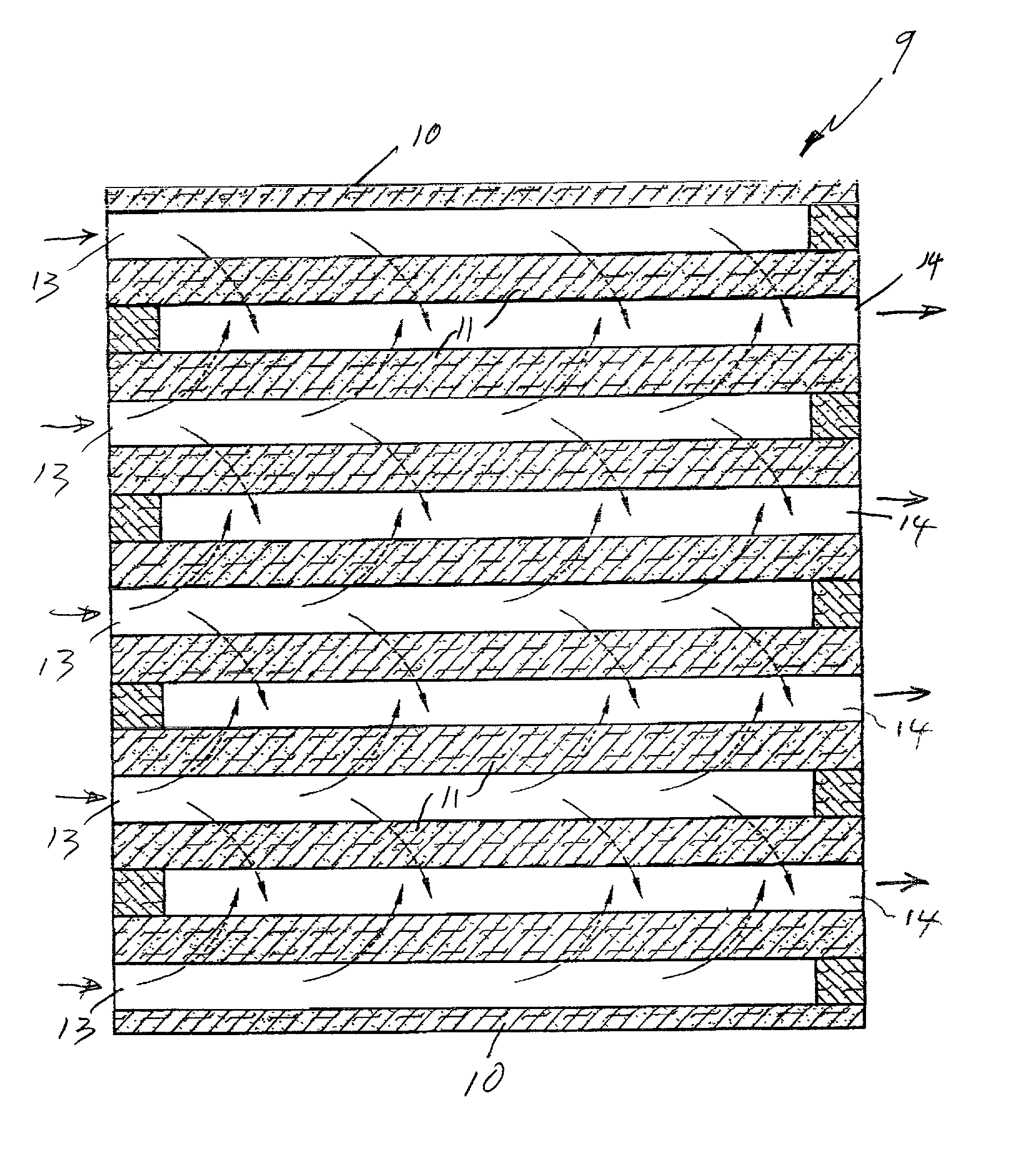
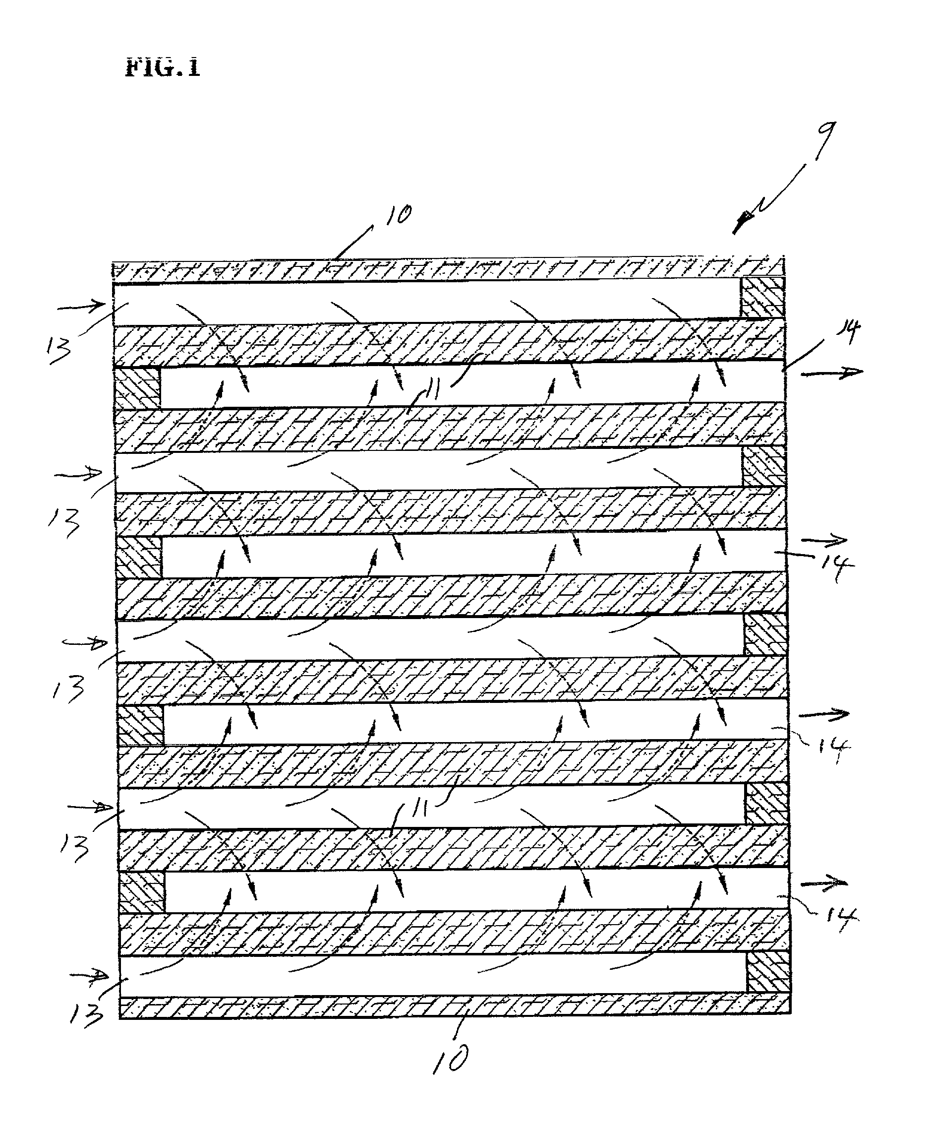
[0012] FIG. 1 is a simplified illustration of a conventional interdigitated flow field as is illustrated and described more fully in commonly owned, copending U.S. patent application Ser. No. 09 / 542,718 filed on Apr. 4, 2000. As illustrated, the flow field plate 9 has end ridges 10 and additional ridges 11 which separate the flow field plate 9 into inlet channels 13 and outlet channels 14. The flow, as is shown by the arrows in FIG. 1, is from the inlet channels, beneath the intermediate ribs 11, and then out through the outlet channels 14. The flow field plate 9 is positioned adjacent to an additional, porous plate of the fuel cell, typically a reactant support plate, into which reactant is forced by convection as it flows beneath the intermediate ribs 11. A greater concentration of the reactant gas reaches the adjacent, porous electro catalyst support plate by means of the forced convention created by the interdigitated flow field than is normally achieved simply by diffusion of t...


PUM


Abstract

A fuel cell reactant flow field (16) has flow-through channels (18) joined by an interface (26) with interdigitated flow channels (21, 22). The interface may be defined by a flow reversing manifold (35) or may exist between flow reversing manifolds (43, 48), remotely thereof.

Description

[0001] This invention relates to reactant flow fields in a fuel cell having partly low pressure flow through reactant flow field channels and partly interdigitated flow field channels.[0002] The electrochemical reactions in fuel cells are well known. The reactants in alkaline, acid, or solid polymer electrolyte fuel cells are hydrogen or a hydrogen rich fuel at the anode, and an oxygen or air oxidant at the cathode. It is known to use interdigitated reactant flow fields to minimize concentration polarization within fuel cells operating with dilute reactants.[0003] Interdigitated reactant flow fields, in which entrance gas flow channels do not directly connect to exit gas flow channels, thereby force the reactant gas to flow into an adjacent layer of the fuel cell. This results in forced convection of the reactant toward the electro catalyst so that a greater proportion of the reactant flowing through the reactant flow fields is utilized more efficiently. However, the forced convecti...

Claims


Application Information

Patent Timeline
IPC IPC(8): H01M8/02H01M8/24
CPCH01M8/023H01M8/0247H01M8/0258Y02E60/50H01M8/2483
Inventor MARGIOTT, PAUL R.
Owner AUDI AG
Why Eureka
Try Eureka