Baw filters having different center frequencies on a single substrate and a method for providing same

a technology of acoustic wave resonators and substrates, which is applied in the manufacture/assembly of piezoelectric/electrostrictive devices, piezoelectric/electrostrictive devices, and sound producing devices. it can solve the problems of unavoidably large modules, high cost, and inability to teach how to overcom

Inactive Publication Date: 2002-07-11
AVAGO TECH WIRELESS IP SINGAPORE PTE
View PDF0 Cites 11 Cited by
  • Summary
  • Abstract
  • Description
  • Claims
  • Application Information

AI Technical Summary

Problems solved by technology

However, although it is known in the art to provide both BAW resonators of a single-stage filter on a single substrate, or several such pairs making up a ladder filter on a single substrate, the prior art does not teach how to overcome the obstacle of fabricating on a single substrate several BAW filters with substantially different center frequencies and so having substantially different thicknesses of the piezolayer.
Instead, the prior art teaches fabricating different filters (with substantially different center frequencies) on different substrates, and then combining the individually packaged filters into one module, a module that is unavoidably larger and usually more costly than a single-substrate multi-band filter.

Method used


Image

  • Baw filters having different center frequencies on a single substrate and a method for providing same
  • Baw filters having different center frequencies on a single substrate and a method for providing same
  • Baw filters having different center frequencies on a single substrate and a method for providing same

Examples


Embodiment Construction

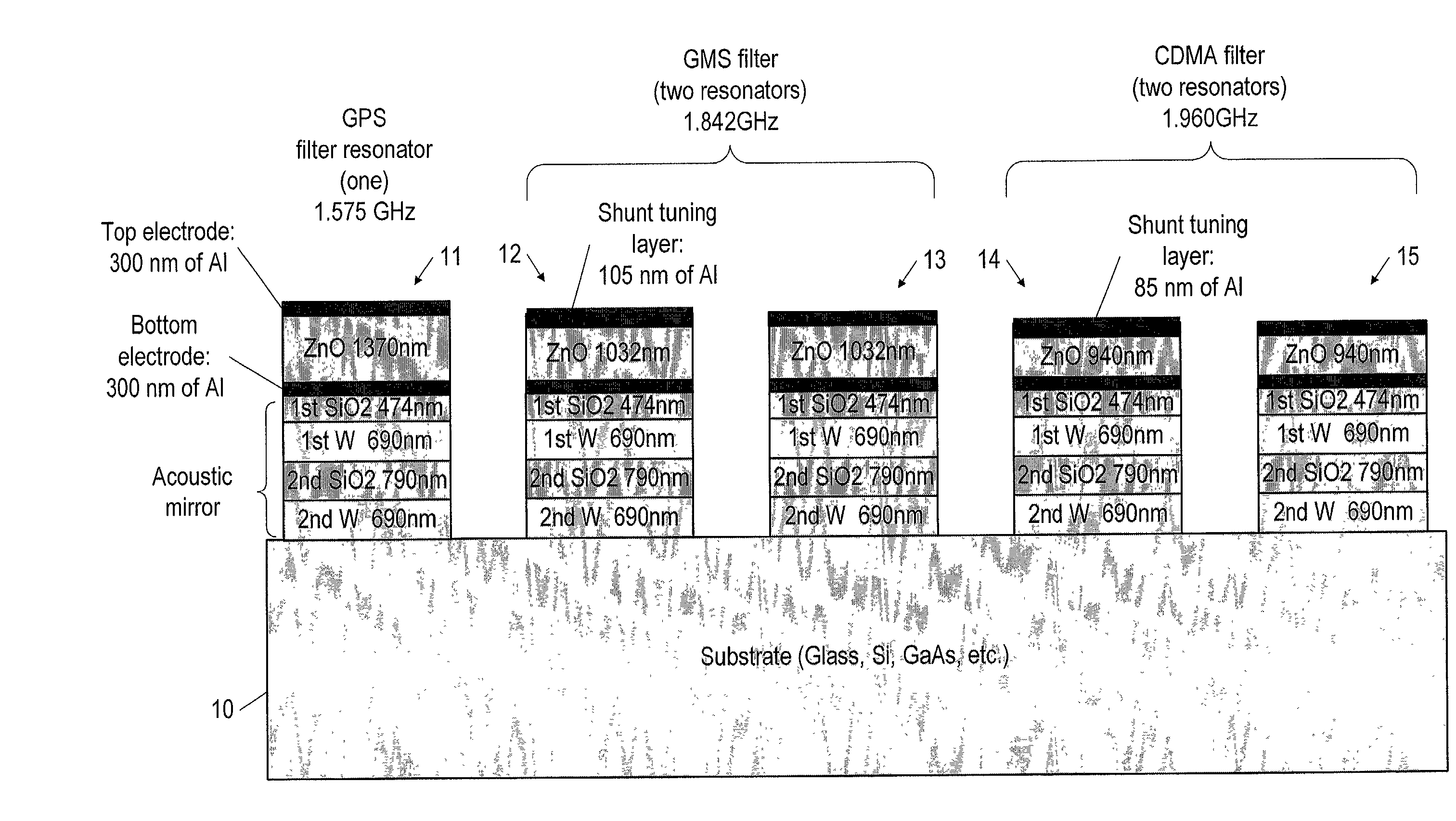
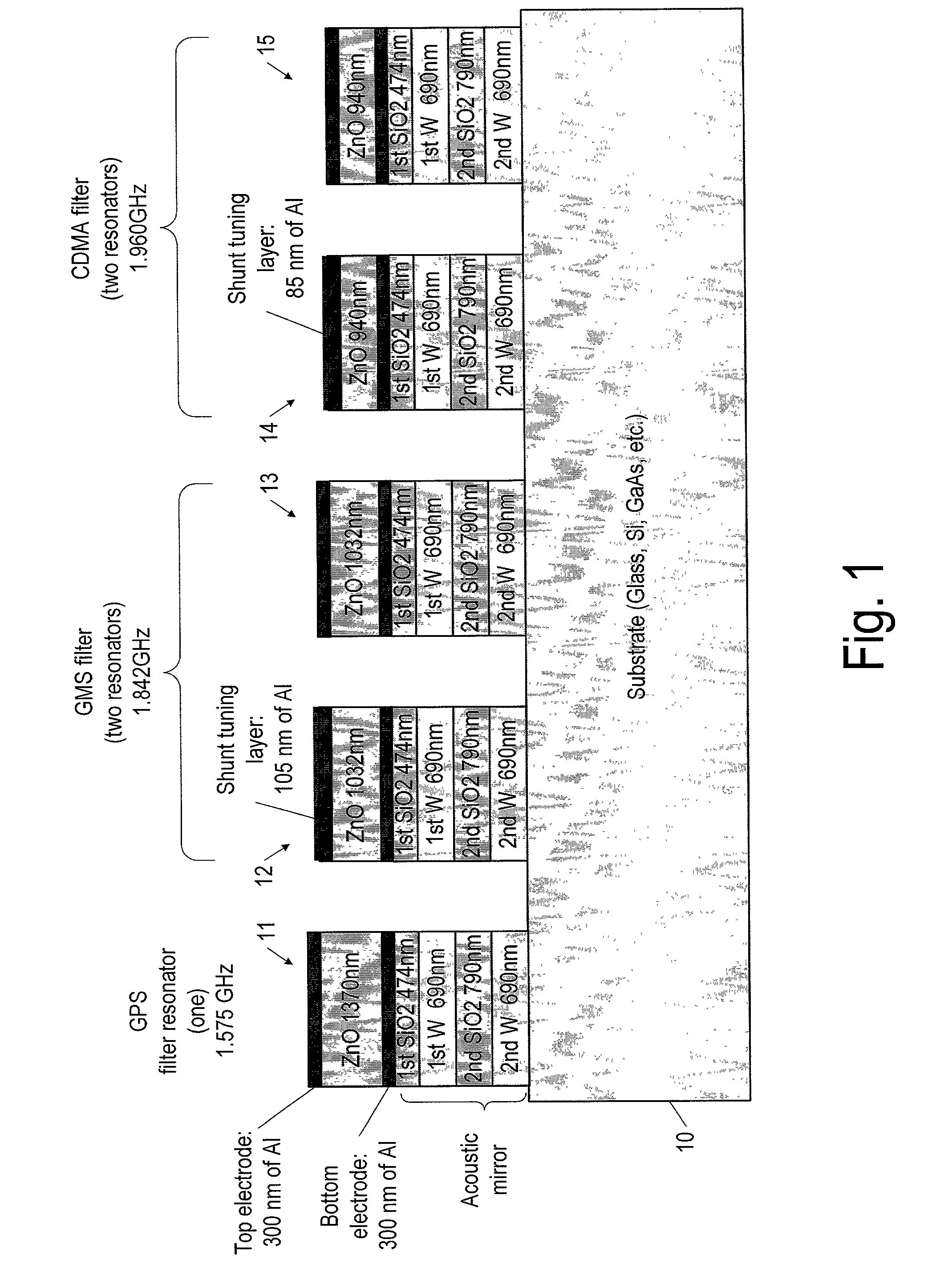
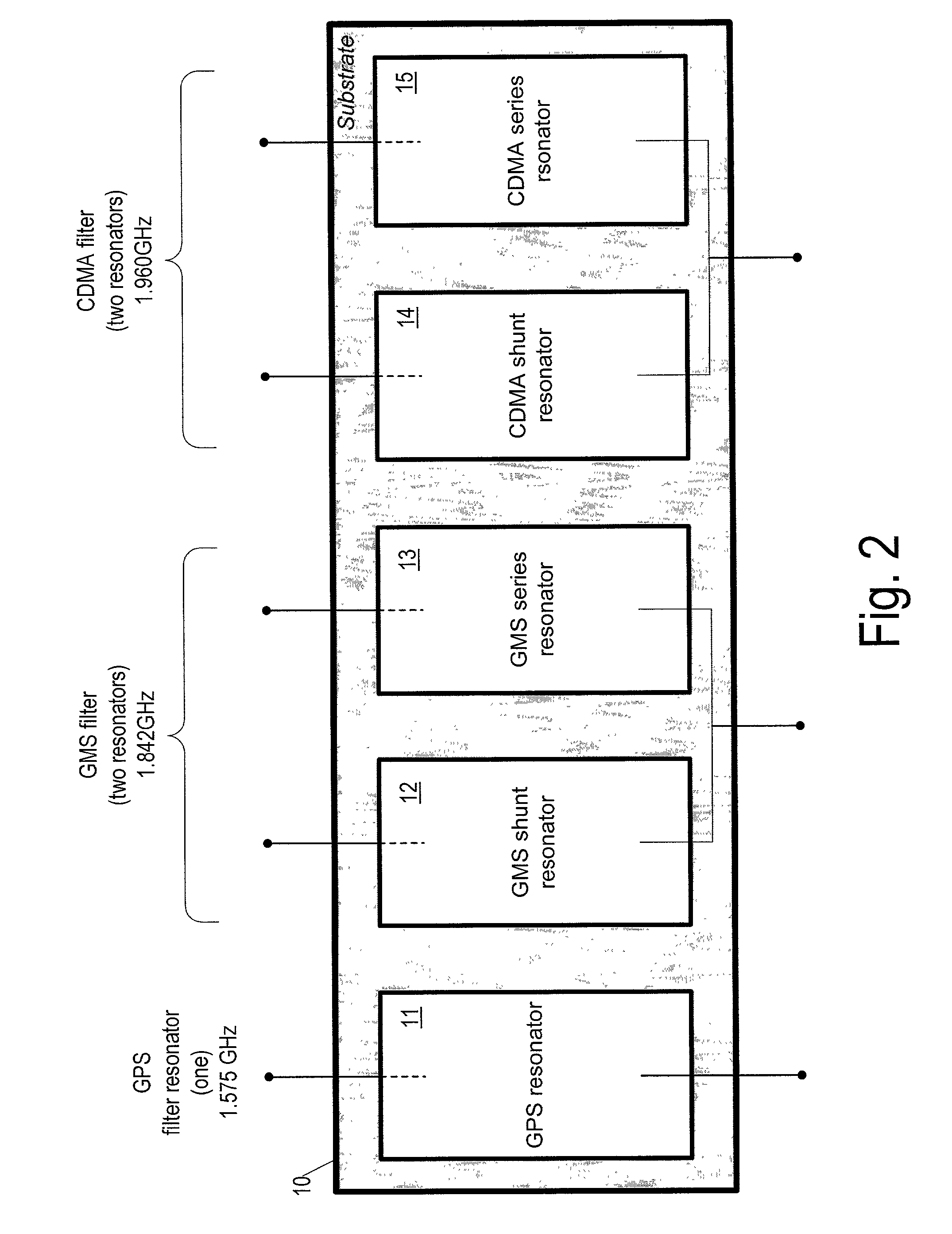
[0024] Referring now to FIGS. 1-3, the invention will now be described for the particular application of a multi-band bulk acoustic wave (BAW) filter 30 (FIG. 3) consisting of a Global Positioning System (GPS) filter 31 with a passband centered at 1.575 GHz, a GMS filter 32 with a passband centered at 1.842 GHz, and a code division multiple access (CDMA) filter 33 with a passband centered at 1.960 GHz. The GPS filter uses only a single BAW resonator 11 in combination with a capacitor 34 to form what is called an L-section of a filter, whereas the two other filters 32 33 each include two BAW resonators 12-15, a series BAW resonator 13 15 and a shunt BAW resonator 12 14, each pair of such filters forming an L-section. (Actually, for clarity, FIGS. 1-3 show only one of each of three filters actually used, with the GPS filter using three L-sections connected in series so as to form a ladder filter, each L-section consisting of a resonator and a capacitor and with the GMS and CDMA filter...


PUM

PropertyMeasurementUnit
thicknessaaaaaaaaaa
thicknessaaaaaaaaaa
thicknessaaaaaaaaaa

Abstract

A method of fabricating a plurality of bulk acoustic wave (BAW) resonators on a single substrate, and the corresponding product, the BAW resonators having substantially different resonant frequencies, the method including the steps of: providing a substrate having an upper facing surface; depositing an isolation structure on the upper facing surface of the substrate; depositing a first metallic layer on the isolation structure, the first metallic layer serving as a bottom electrode; and depositing piezolayer material on the bottom electrode so as to have thicknesses corresponding to each of the different resonant frequencies, each different thickness located in a location where a resonator having a resonant frequency corresponding to the thickness is to be located. In one of several embodiments, the step of depositing piezolayer material on the bottom electrode itself includes the steps of: depositing piezolayer material to a thickness corresponding to the lowest frequency resonator; providing hard mask material over areas where the lowest frequency resonators are to be located; and removing the piezolayer material down to the thickness of the next higher frequency resonators. In some applications of the method, the isolation structure is an acoustic mirror, and the method further includes the step of providing the acoustic mirror, interposed between the substrate and the bottom electrode, according to a design that imparts to the acoustic mirror a desired reflection coefficient over a predetermined range of frequency including the substantially different resonant frequencies.

Description

FIELD OF THE INVENTION[0001] The present invention pertains to the field of fabricating bulk acoustic wave resonators, and more particularly to the field of fabricating, on a single substrate, more than one filter, each filter including at least two such resonators.BACKGROUND OF THE INVENTION[0002] It is known in the art to provide a so-called bulk acoustic wave (BAW) resonator, which includes a piezolayer sandwiched between two metallic layers that serve as electrodes. Such an assembly has a resonant frequency, with the thickness of the piezolayer the predominant factor in determining the resonant frequency, and so is often used as a component of a radiofrequency (RF) filter, as in for example mobile phone equipment. A typical example of such a filter is the so-called ladder filter, which often includes two such resonators, a series resonator (placed in series with the signal to be filtered) and a shunt resonator (shunting the signal to be filtered), and in fact can include a serie...

Claims


Application Information

Patent Timeline
Patent Type & Authority Applications(United States)
IPC IPC(8): H01L41/09G10K11/04H01L41/22H01L41/331H01L41/332H03H3/02H03H3/04H03H9/17H03H9/54H03H9/58
CPCH03H3/04H03H9/589H03H2003/0428H03H2003/0435H03H2003/0471Y10T29/42
Inventor ELLA, JUHAPOHJONEN, HELENA
Owner AVAGO TECH WIRELESS IP SINGAPORE PTE
Why Eureka
Try Eureka