Supercharge Your Innovation With Domain-Expert AI Agents!

Fuel pressure regulating valve

a technology of fuel pressure, which is applied in the direction of fluid pressure control, process and machine control, instruments, etc., can solve the problems of noise generation, uneven pressure distribution, and noise generated in the fuel pressure regulating valv

Inactive Publication Date: 2002-07-18
DENSO CORP +1
View PDF7 Cites 19 Cited by
  • Summary
  • Abstract
  • Description
  • Claims
  • Application Information

AI Technical Summary

Benefits of technology

[0017] In order to achieve the object mentioned above, a fuel pressure regulating valve in accordance with the present invention is structured such that a flow collision preventing means for preventing a collision of a flow of a fuel flowing from respective portions in an annular gap formed between a valve body and a valve seat toward a central direction of an opening portion of a bush is provided in the bush. In accordance with this structure, since the collision of the fuel of the fuel flowing from the respective portions in the annular gap formed between the valve body and the valve seat toward the central direction of the opening portion of the bush is prevented by the flow collision preventing means, a positive pressure area generated by the collision of the flow of the fuel is not generated. Accordingly, a pulsation pressure of the positive pressure is not applied to a lower surface of the valve body, a phenomenon that the valve body and a diaphragm vibrate is restricted, and it is possible to reduce a noise due to a resonance of a spring introduced by a vibration transmission and a noise due to a resonance of a fuel pipe and a fuel tank.
[0018] In this case, the flow collision preventing means may be integrally formed with the bush, however, it is preferable that the structure is made such that a flow collision preventing means independently formed from the bush is fitted to the opening portion of the bush, a part of the flow collision preventing means is protruded to a side of the valve body rather than the valve seat, and a runoff recess portion running off a protruding portion of the flow collision preventing means is formed in the valve body. In accordance with this structure, a shape of the bush may be the same as the conventional one, and it is not necessary to change a design of the shape of the bush. Further, it is possible to improve an accuracy of concentricity between the flow collision preventing means and the bush by an engagement between the both, it is further possible to avoid an interference and a collision between the valve body and the flow collision preventing means by the runoff recess portion formed in the valve body, and it is possible to closely attach the valve body to the valve seat of the bush in a secure manner.
[0019] Further, the structure may be made such that a flow passage or a hole for flowing the fuel flowing from the annular gap formed between the valve body and the valve seat in an axial direction along an inner peripheral surface of the bush is formed in the flow collision preventing means. In accordance with the structure mentioned above, since it is possible to flow the fuel in the axial direction along the inner peripheral surface of the bush while preventing the collision of the flow of the fuel within the bush, it is possible to reduce a peel-off of the flow of the fuel near the inner peripheral surface of the bush so as to reduce the negative pressure due to the peel-off of the flow of the fuel, it is possible to restrict the vibration due to the pulsation of the negative pressure, and it is possible to further increase the noise reduction effect.

Problems solved by technology

In a motor car in recent years, a quiet property becomes important, and in accordance with a progress of the quiet property, a noise generated in the fuel pressure regulating valve generates a problem as a new noise source.
Further, there is a case that the noise is generated due to the pulsation resonation with respect to the equipment arranged in a downstream side of the outflow port 19.
That is, the pressure distribution is uneven.
As a result, the pulsation resonance is generated between the equipment and the fuel pressure regulating valve, and the noise is also generated due to this noise.
Accordingly, the fuel pressure regulating valve in the publication mentioned above is effective in the case that the fuel flow amount exists within the specific range, however, it is difficult to say that the fuel pressure regulating valve is effective in every fuel flow amount.
That is, when the collision of the fuel is generated in the upstream side, the pressure distribution of the fuel becomes uneven.
Further, the flow of the fuel is throttled by these flow passages or holes.
Further, due to the uniformization of the pressure distribution, the negative pressure area is hard to appear in the downstream side of the pressure uniformizing partition wall portion.
Accordingly, a severe dimensional accuracy is required in the valve seat.
Accordingly, a severe dimensional accuracy is also required in the pressure uniformizing partition wall portion.
Accordingly, when flowing the fuel after expansion into the pressure uniformizing partition wall portion, there is a risk that the pulsation is generated due to the throttle resistance of the flow passage or the hole.

Method used


Image

  • Fuel pressure regulating valve
  • Fuel pressure regulating valve
  • Fuel pressure regulating valve

Examples


embodiment 1

[0062] A description will be given below of an embodiment 1 in accordance with the present invention with reference to FIGS. 1 to 4.

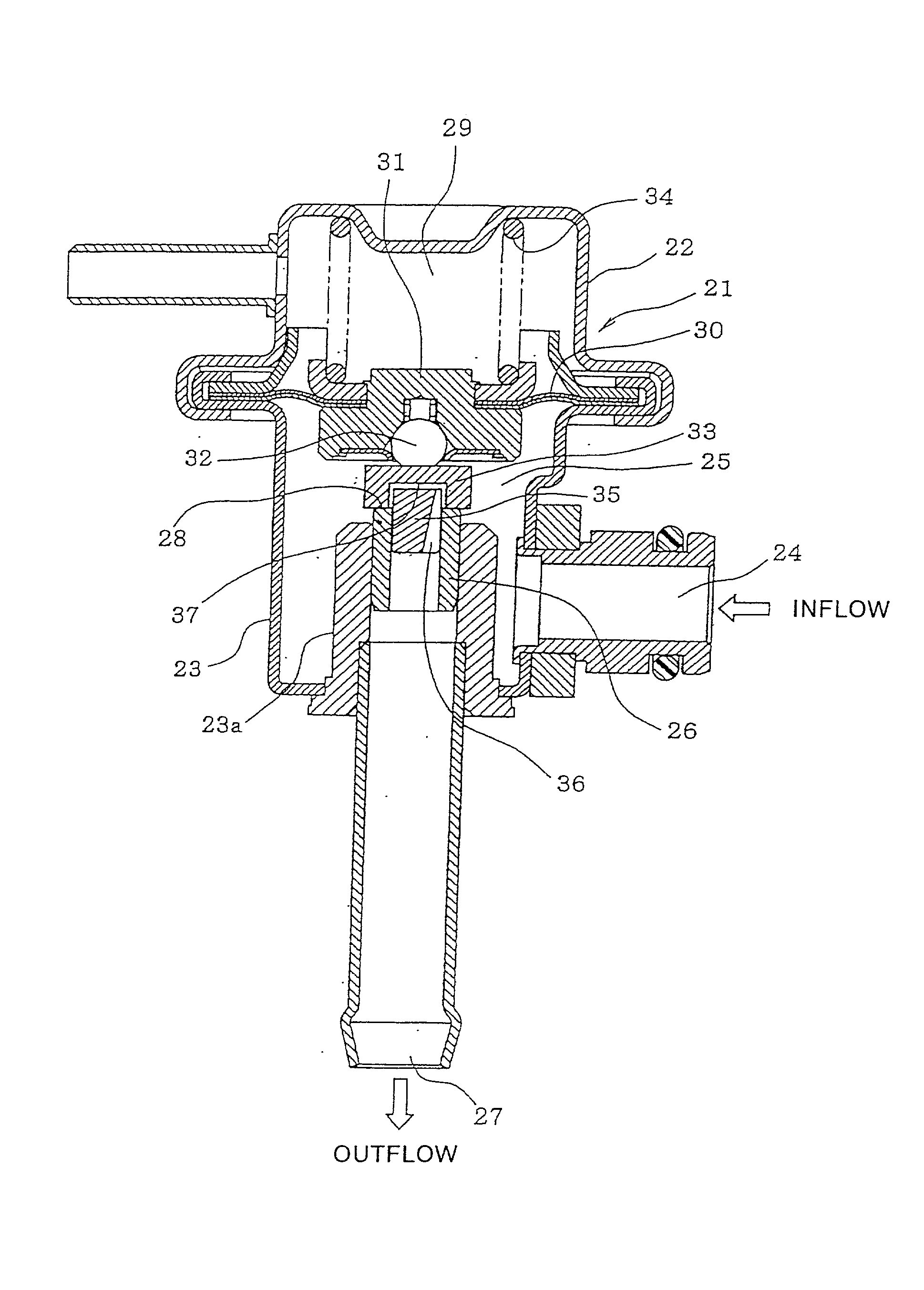
[0063] As shown in FIG. 1, a housing 21 of a fuel pressure regulating valve is constructed by connecting an upper housing 22 to a lower housing 23 in accordance with a caulking operation or the like, and a fuel chamber 25 into which a fuel discharged from a fuel pump (not shown) flows from an inflow port 24 is formed within the lower housing 23. A cylindrical bush 26 is fitted and fixed within a small diameter tube portion 23a provided in a lower portion of the lower housing 23 in a vertical direction, and an outflow port 27 is provided in a lower portion of the small diameter tube portion 23a. A valve seat 28 is formed on an upper end surface (a peripheral edge of an opening portion) of the bush 26.

[0064] On the contrary, a spring chamber 29 is formed within the upper housing 22, and the spring chamber 29 and the fuel chamber 25 are partitioned by a di...

embodiment 2

[0077] In accordance with the present embodiment 2 described above, since the pressure partition wall portion 41 partitioning the low pressure area within the bush 26 and the high pressure area near the lower surface of the valve body 33 is fitted to the upper end opening portion of the bush 26, an application of the pressure pulsation to the valve body 33 is shut off by the pressure partition wall portion 41 even if the positive pressure area due to the collision of the fuel or the negative pressure area due to the peel-off of the flow is generated within the bush 26 (the low pressure area). Accordingly, the phenomenon that the valve body 33 and the diaphragm 30 vibrate is restricted, and it is possible to reduce the noise due to the resonance of the spring 34 introduced by the vibration transmission and the noise due to the resonance of the fuel pipe and the fuel tank.

[0078] Further, in accordance with the present embodiment 2, since the inflow hole 42 formed in the pressure parti...

embodiment 3

[0085] In accordance with the present embodiment 3, the pressure uniformizing partition wall portion 50 provided with the holes 51 is fitted to the upper portion in the inner peripheral side of the bush 26. Accordingly, even when the collision of the fuel is generated in the upstream side of the pressure uniformizing partition wall portion 50 and the pressure distribution becomes uneven, it is possible to divide the fuel by twelve holes 51. Further, in accordance with this flow division, it is possible to uniformize the pressure distribution of the fuel again combined in the downstream side of the pressure uniformizing partition wall portion 50. Further, due to a throttle loss of the holes 51, it is possible to reduce the flow speed of the fuel.

[0086] Further, in accordance with the present embodiment 3, since the upper end surface of the pressure uniformizing partition wall portion 50 is arranged immediately below the valve seat 28, a severe dimensional accuracy is not required eve...


PUM


Abstract

There is disclosed a pressure regulating valve which effectively reduces a noise of a fuel pressure regulating valve without relation to a flow amount of a fuel. In this valve, a flow collision preventing member (35) is fitted to an upper end opening portion of a bush (26), and an upper portion of the flow collision preventing member (35) is protruded to a side of a valve body (33) rather than a valve seat (28) (an upper end surface of the bush (26)). A plurality of flow passages (36) for flowing the fuel in an axial direction thereof (in a downward direction) along an inner peripheral surface of the bush (26) are formed in an outer peripheral portion of the flow collision preventing member (35) with a uniform interval. A runoff recess portion (37) running off a protruding portion of the flow collision preventing member (35) is formed in the valve body (33) positioned immediately above the valve seat (28). Since the upper portion of the flow collision preventing member (35) protrudes out to an inner peripheral side of an annular gap formed between the valve body (33) and the valve seat (28), a collision of a flow of the fuel flowing through respective portions of the annular gap toward the inner peripheral direction is prevented by the flow collision preventing member 35, a pressure pulsation due to the collision of the flow of the fuel is not generated in a lower side of the valve body 33, and a noise due to the pressure pulsation is reduced.

Description

[0001] 1. Field of the Invention[0002] The present invention relates to a fuel pressure regulating valve provided with a means for reducing a noise.[0003] 2. Description of the Related Art[0004] In a motor car in recent years, a quiet property becomes important, and in accordance with a progress of the quiet property, a noise generated in the fuel pressure regulating valve generates a problem as a new noise source.[0005] A conventional fuel pressure regulating valve is generally structured, as shown in FIG. 17, such that a fuel chamber 12 into which a fuel discharged from a fuel pump flows from an inlet port 11 and a spring chamber 14 receiving a spring 13 are formed within a housing 10 so as to be separated by a diaphragm 15, a tubular bush 16 flowing out the fuel within the fuel chamber 12 is provided, a valve body 17 mounted to the diaphragm 15 is opposed to a valve seat 18 formed in a peripheral edge of an opening portion of the bush 16, and the valve body 17 is energized in a d...

Claims


Application Information

Patent Timeline
Patent Type & Authority Applications(United States)
IPC IPC(8): F16K47/00F02M69/54F16K47/02G05D16/06
CPCF02M69/54F16K47/02G05D16/0658Y10T137/7836
Inventor MURAMATSU, TOSHIHIKOFURUKAWA, TAKASHITAKASE, SHINJI
Owner DENSO CORP
Features
  • R&D
  • Intellectual Property
  • Life Sciences
  • Materials
  • Tech Scout
  • Unparalleled Data Quality
  • Higher Quality Content
  • 60% Fewer Hallucinations
Learn More