Eureka AIR delivers breakthrough ideas for toughest innovation challenges, trusted by R&D personnel around the world.

Digital vibration transducer

Inactive Publication Date: 2002-07-18
K & H INNOVATIONS
View PDF24 Cites 16 Cited by
  • Summary
  • Abstract
  • Description
  • Claims
  • Application Information

AI Technical Summary

Benefits of technology

[0011] It is therefore an object of the present invention to provide a versatile vibration transducer for converting a vibration of a vibration member directly into a digital signal.

Problems solved by technology

The art of analog transducers, such as generally used for speakers and microphones, suffers from a number of limitations.
Among these limitations are dynamic range, distortion and, for microphones especially, noise.
Thus, while the human ear can easily have an overall dynamic range of 120 dB and can, in a quiet room, hear a pin drop at one time and at another time accurately hear the notes playing at a 120 dB rock concert, it cannot hear both sounds simultaneously.
But one cannot then expect the same microphone, at the same gain, to cleanly detect sound at 120 dB.
Conversely, an analog microphone attenuated enough to detect a 120 dB concert without clipping, that is cutting off the peaks of the waveforms, would be too insensitive to detect even normal conversation adequately.
Like the human ear, an analog microphone cannot detect both a very loud sound and a soft sound simultaneously.
The second limitation of analog sound transducers is distortion, which has a relationship to dynamic range.
Thus, the louder the sound entering a microphone or leaving a speaker, for example, the more likely it is to distort.
A major source of this distortion is non-linear effects in the suspension of the sound sensing or sound invoking membrane.
It is well known that sound passing through a non-linear medium will suffer distortion as a result, and if the sound is composed of more than one frequency inter-modulation (IM) distortion results causing the introduction of tones not included in the original signal.
Additionally, analog transducers are subject to a lot of noise, such as often generated by the conversion of the data to electrical signal.
However, the sensitivity of the device is severely limited by the provision of a mirror directly on the vibrating membrane, which does not provide any amplification of the original signal.
The lever effect provided by this set up is however limited, and so is the sensitivity of the device.
In addition, the encoding method used by FULENWIDER is complex and would not be appropriate for many typical applications.
None of the above prior art patents however provides a versatile digital vibration transducer alleviating the drawbacks of their analog counterparts.

Method used


Image

  • Digital vibration transducer
  • Digital vibration transducer
  • Digital vibration transducer

Examples


first embodiment

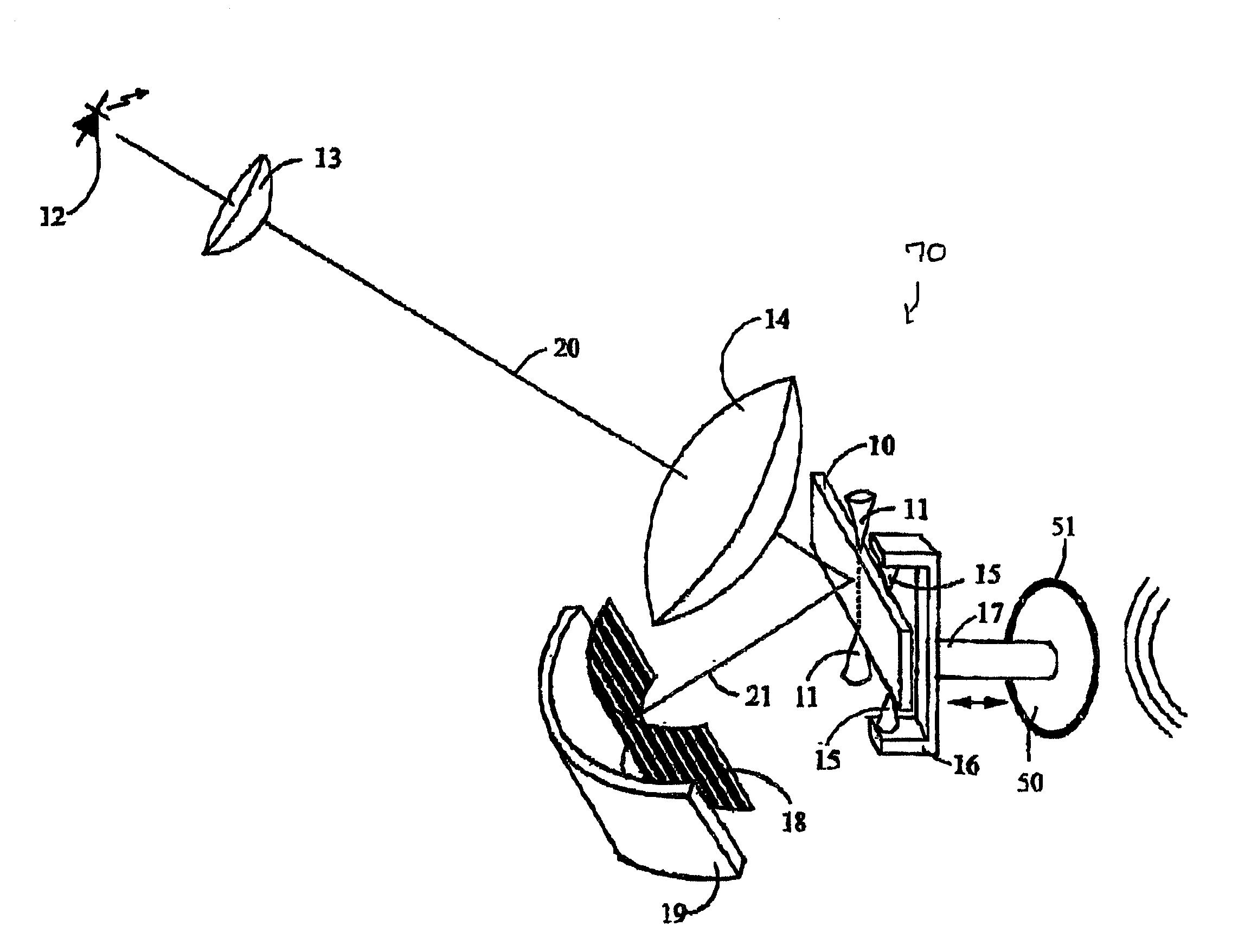
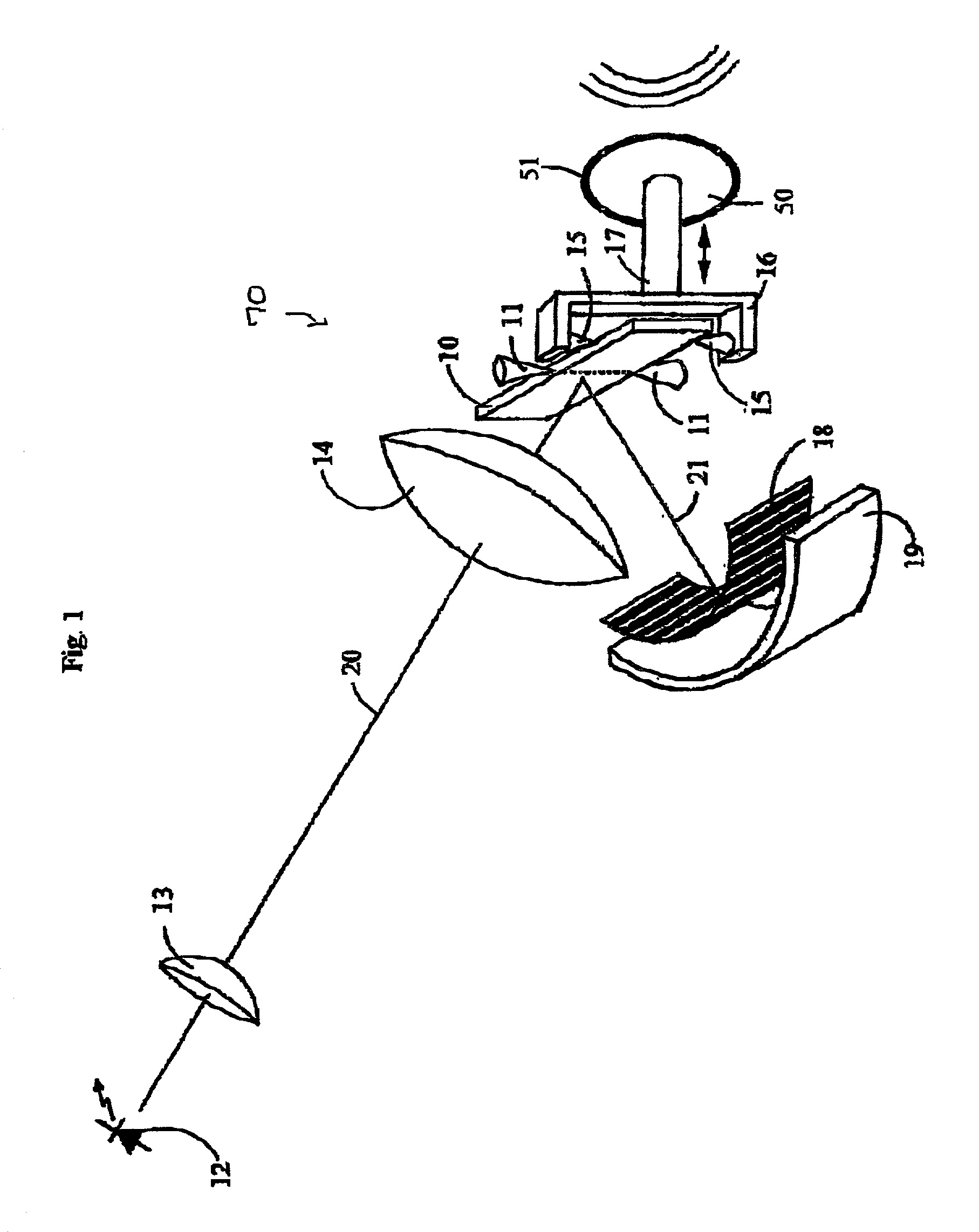
[0033] Referring to FIGS. 1 and 2, there is shown a transducer (70) according to the present invention. In this particular case, the reflector is embodied by a surface mirror (10) made pivotable through suspension between two "vee" bearings (11). These bearings are aligned to allow pivoting of the mirror about a vertical pivot axis, which is preferably horizontally centered on the mirror. The bearings are preferably held in position by a stationary frame (not shown) firmly mounted to a housing (not shown) which also holds all other non-dynamic components of the system in fixed positions. The frame is presumed to cause the bearings to exert a light pressure on the mirror (10). Since it is desirable, for optimum response and sensitivity, to have as little friction and end play as possible, it is preferable to use high precision jeweled bearings. To assist visualization it may be presumed that tiny holes are provided in the edges of the mirror into which the points of the bearings are ...

third embodiment

[0066] Frequency Response. While the Digital Vibration Transducer (DVT) has no lower frequency limit (this is because the encoding sensor will output pulses no matter how slowly the laser sweeps across it), the upper frequency limit is almost entirely dependent on the mass of the dynamic components. As illustrated in the third embodiment, that mass can be made very low. How low that mass can become is technology dependent and can not be fixed absolutely. It is reasonable to expect that, with present technology, the device can achieve a better than 100 kHz response. The frequency range is dependent on the dynamic range of the device. This is because signals of different frequencies but the same power can vary by orders of magnitude in the amount of diaphragm excursion, and therefore, the amount of laser deflection across the encoding plate, they cause. Thus a 20 kHz signal will produce one millionth of the laser deflection that a 20 Hz signal will produce at the same power. If both t...


PUM


Abstract

A digital vibration transducer for producing a digital signal representative of a vibration of a vibrating member is provided. The transducer includes a laser source producing a light beam that is focused on a detection area. The light beam is reflected towards this detection area by a reflector, at an angle with the optical axis of the light beam and pivotable about a pivot axis. A linkage assembly connects the vibrating member to the reflector to convert the vibrating of the vibration member into a pivoting of the reflector, thereby sweeping the reflected light beam across the detection area. A sensing and encoding assembly is provided in the detection area and produces the digital signal representative of the vibration of the vibrating member relatively to the sweeping of the light beam.

Description

[0001] The present invention relates to the field of transducers and more particularly concerns a vibration transducer that translates the vibration of a vibration source directly into a digital signal.[0002] The art of analog transducers, such as generally used for speakers and microphones, suffers from a number of limitations. Among these limitations are dynamic range, distortion and, for microphones especially, noise.[0003] "Dynamic range" describes the range of volume that a transducer can either detect or produce. A distinction should however be made between overall dynamic range and instantaneous dynamic range. Thus, while the human ear can easily have an overall dynamic range of 120 dB and can, in a quiet room, hear a pin drop at one time and at another time accurately hear the notes playing at a 120 dB rock concert, it cannot hear both sounds simultaneously. This is also true of analog microphones. If one raises the gain of a sensitive analog microphone high enough it can pi...

Claims


Application Information

Patent Timeline
IPC IPC(8): G01H9/00
CPCG01H9/00
Inventor KANE, GERRY M.
Owner K & H INNOVATIONS
Why Eureka
Eureka Blog
Learn More