Spinal needle

a needle and spinal cord technology, applied in the field of spinal needles, can solve the problems of inability to puncture the dura, inability to puncture the spinal cord, and the tip of the conventional epidural or spinal needle may accidentally enter the subdural space, so as to facilitate lumbar puncture procedures, facilitate the manipulation of the introducer, and reduce the loss of csf

Inactive Publication Date: 2002-07-25
ZOHMANN WALTER A
View PDF0 Cites 40 Cited by
  • Summary
  • Abstract
  • Description
  • Claims
  • Application Information

AI Technical Summary

Benefits of technology

0029] This invention is an improved needle for facilitating lumbar puncture procedures. More particularly, the invention is a novel, atraumatic needle apparatus for reducing loss of CSF through the dura puncture hole. The apparatus comprises a sharp, hollow introducer component a few centimeters in length that is used to puncture the skin, having raised tip indicators disposed upon the introducer hub; a more blunt, hollow needle component several centimeters in length that is slideably disposed within the hollow introducer,

Problems solved by technology

The dura and the arachnoid are in such close contact that usually it is not possible to puncture the dura without also piercing the arachnoid.
Nevertheless, on rare occasions, the tip of the conventional epidural or spinal needle may accidentally enter the subdural space.
Local anesthetic inadvertently injected into the subdural space will diffuse poorly and result in inadequate contact with the nerve roots.
Poor or absent anesthesia may ensue.
Should subdural placement occur during an attempted epidural anesthetic, the improper position of the needle may not be recognized and the injection of an epidural dose of local anesthetic may result in a much higher block than anticipated.
However, the incidence of postspinal headache is increased with the larger needle, particularly if the larger needle is also equipped with a standard point which is a cutting bevel.
Bringing the patient into the erect position also results in traction on the pain-sensitive, dilated blood vessels.
The common practice of keeping the patient supine for 4 to 24 hours after lumbar puncture has been shown to be ineffecti

Method used


Image

  • Spinal needle
  • Spinal needle
  • Spinal needle

Examples


Embodiment Construction

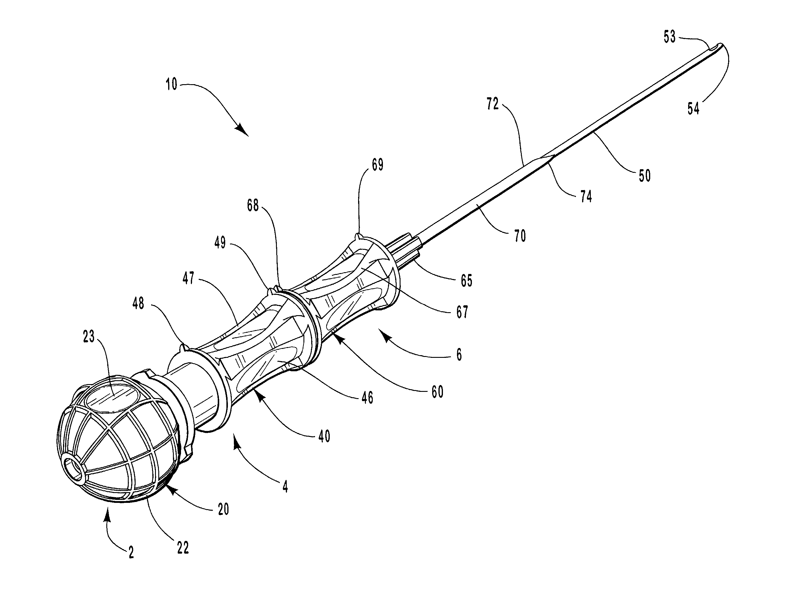
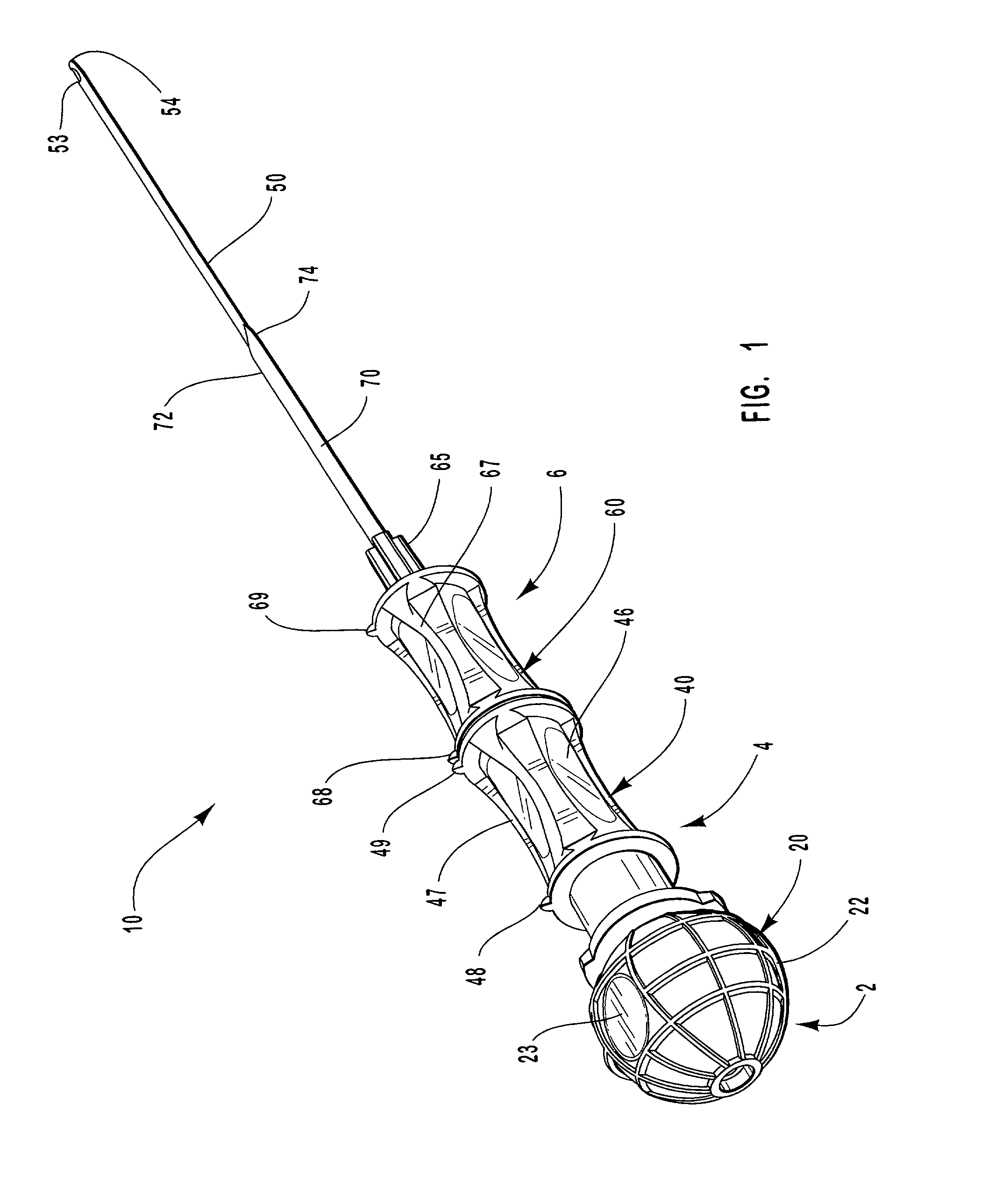
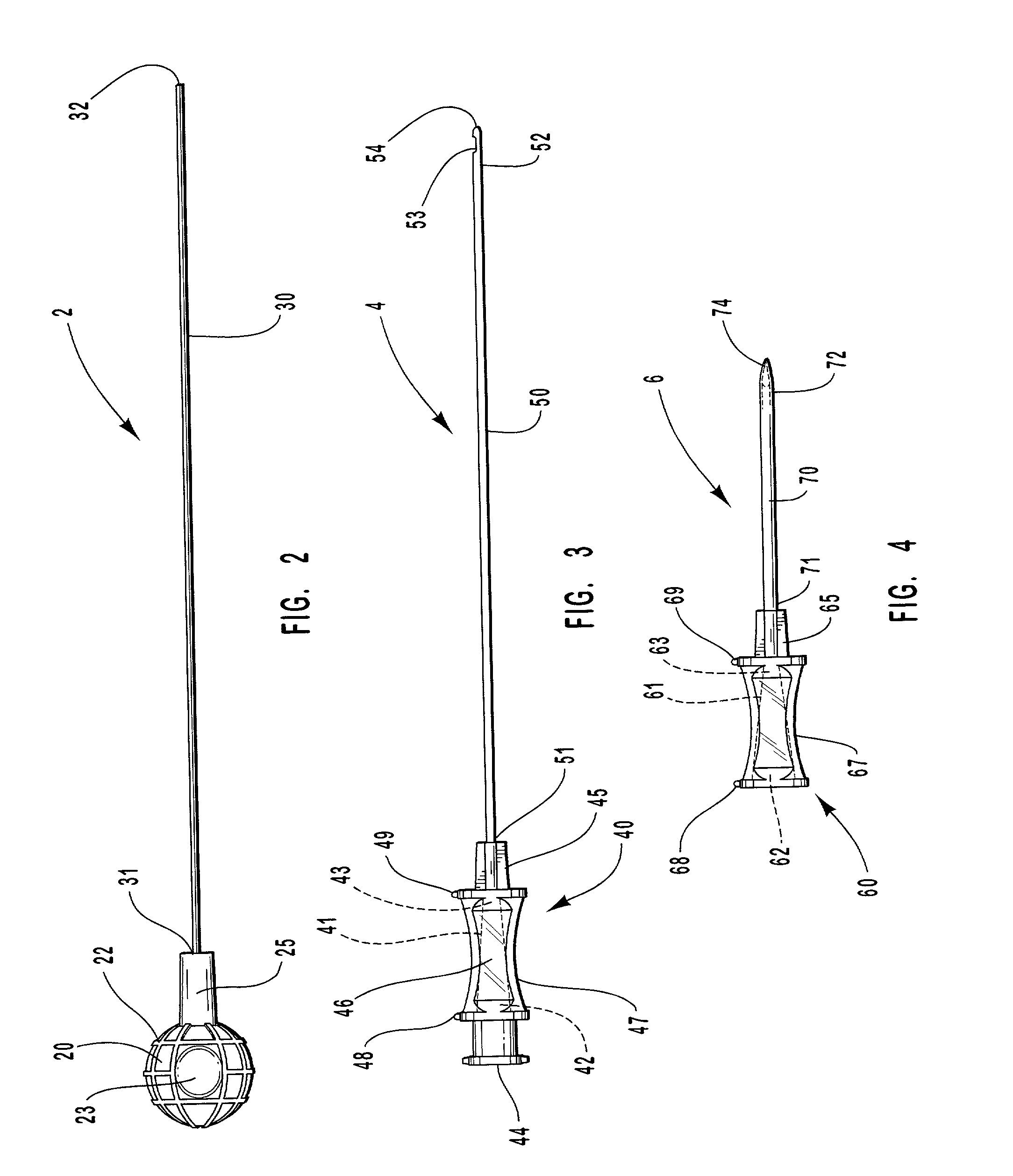
[0061] In one embodiment of the present invention, a spinal anesthetic delivery device comprises three components. A sharp, hollow introducer component a few centimeters in length that is used to puncture the skin, a more blunt hollow needle component that is several centimeters in length that is slideably disposed within the hollow introducer to allow the caregiver to delicately pierce the dura membrane, and a stylet component that is slideably disposed within the introducer to selectively occlude the needle and control the flow of fluid therein. The introducer and needle components both have relatively small transparent hubs on their proximate ends. The hubs act as handles or grips to facilitate manipulation of the introducer and needle and allow the caregiver to view fluids passing into or out of them.

[0062] Using the present invention, a care giver administers a lumbar puncture procedure following the steps typically used in procedures well-known in the art, but includes the adv...


PUM


Abstract

The present invention is directed toward an improved spinal needle. A needle hub is disposed about a proximate end of a hollow needle. The needle hub side port indicators provide visual and tactual verification by a user of the orientation of the side port on the needle. The needle hub also includes a window with a magnified view. The invention provides a stylet cap disposed about a proximate end of a stylet that freely slides inside the hollow needle and needle hub. The stylet cap forms a pressure fit with the needle hub, and can be engaged in the pressure fit from any axial orientation.

Description

[0001] 1. Field of the Invention[0002] This invention relates to innovative needles for facilitating lumbar puncture procedures generally and, more particularly, to a novel, atraumatic needle apparatus and method for reducing loss of cerebral spinal fluid (CSF) during such procedures.[0003] 2. Background[0004] Spinal anesthesia is one of the most frequently employed methods of regional anesthesia. This regional anesthesia is accomplished by the temporary interruption of nerve transmission using a local anesthetic injected into the readily identifiable subarachnoid space. The ensuing anesthesia is predictable, occurs rapidly, and is associated with profound muscle relaxation. The patient may be wide awake, or if preferred, the anesthetic may be supplemented with varying amounts of sedative-tranquilizers. Spinal anesthesia is particularly useful for surgery involving the lower extremities, pelvis, perineum, and lower abdomen.[0005] The spinal column, which surrounds the spinal cord, i...

Claims


Application Information

Patent Timeline
IPC IPC(8): A61B17/00A61B17/34
CPCA61B17/3401A61B2017/00424A61B2017/00455
Inventor ZOHMANN, WALTER A.
Owner ZOHMANN WALTER A
Why Eureka
Try Eureka