BOP operating system with quick dump valve

a technology of operating system and dump valve, which is applied in the direction of sealing/packing, instruments, borehole/well accessories, etc., can solve the problems of increasing the time required to close the shear ram and disconnect the lmrp from the bop stack, high differential pressure, and consuming valuable seconds

Inactive Publication Date: 2002-08-01
PROSERV GILMORE VALVE LLC +1
View PDF0 Cites 37 Cited by
  • Summary
  • Abstract
  • Description
  • Claims
  • Application Information

AI Technical Summary

Problems solved by technology

This circuitous hydraulic vent path results in a high differential pressure, which decreases flow of control fluid through the close side of the operating system.
The decreased flow consumes valuable seconds, and as such, increases the time required to close the shear rams and disconnect the LMRP from the BOP stack.
Some BOP hoses may collapse in deep water when subjected to high velocity flows of hydraulic fluid resulting from functioning of the BOPs with large capacity operators.
Hose collapse is, of course, undesirable.
Maintenance on prior art BOP operating systems is sometimes lengthy and expensive.
This circuitous hydraulic vent path on the close side of prior art operating systems results in a high differential pressure, which decreases flow of control fluid when the rams are being closed.
The decreased flow consumes valuable seconds and, as such, increases the time required to close the rams and disconnect the LMRP from the BOP stack.
The cracking pressure of the check valve results in the differential pressure and force required to energize the metal to metal face seal.

Method used


Image

  • BOP operating system with quick dump valve
  • BOP operating system with quick dump valve
  • BOP operating system with quick dump valve

Examples


Embodiment Construction

is provided in the appended drawings. It is noted, however, that the appended drawings illustrate only a typical embodiment of this invention and are therefore not to be considered limiting of its scope, for the invention may admit to other equally effective embodiments. Reference the appended drawings, wherein:

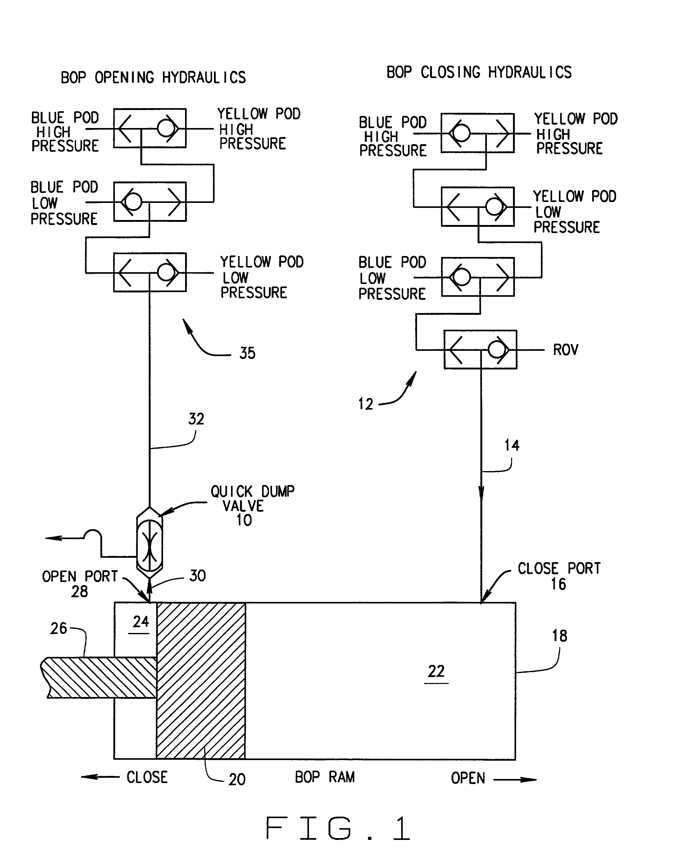
[0020] FIG. 1 is a hydraulic circuit showing the BOP rams in the closed position and the quick dump valve of the present invention in the vent position.

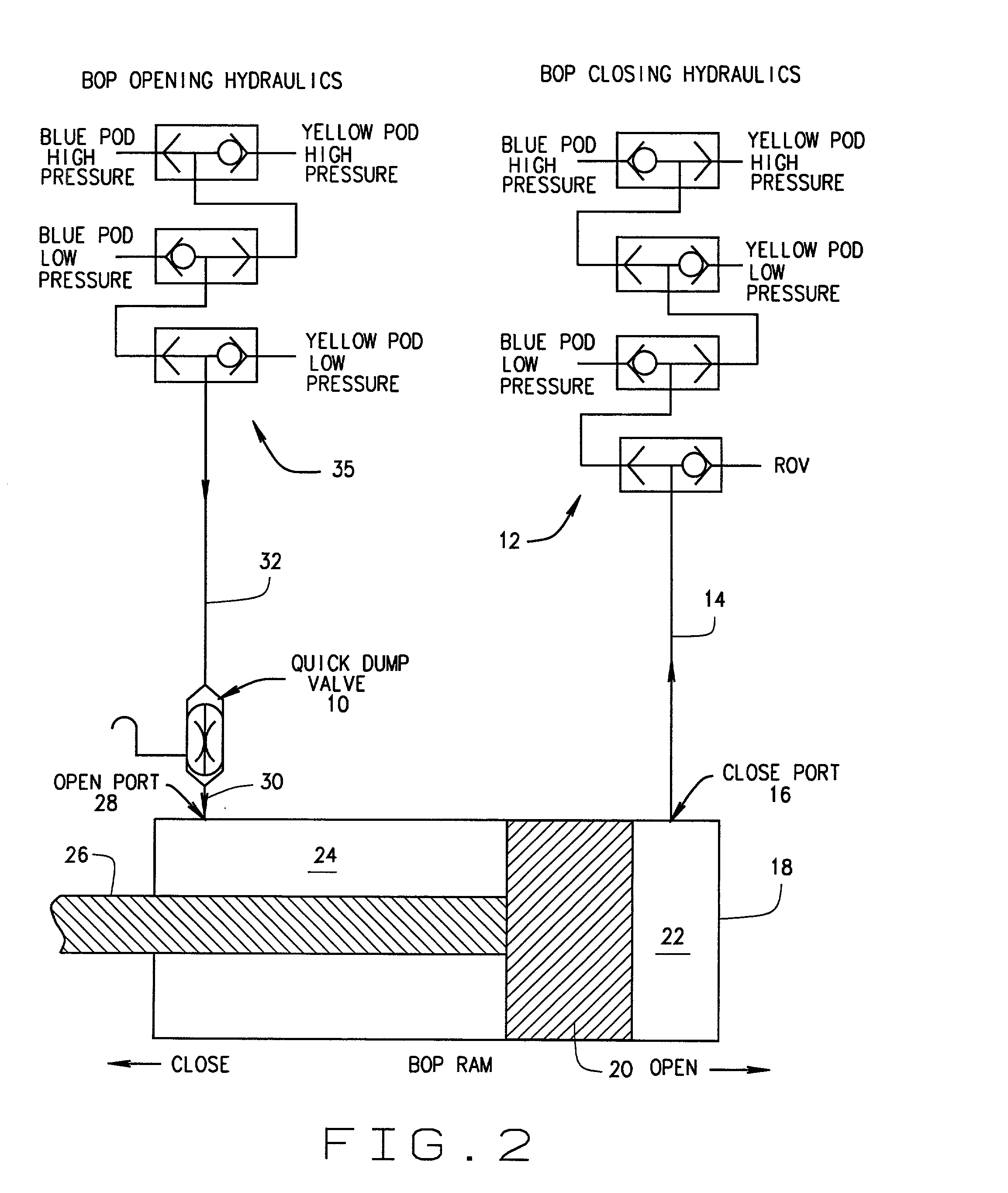
[0021] FIG. 2 is a hydraulic circuit showing the BOP rams in the open position and the dump valve of the present invention in the open position.

[0022] FIG. 3 is a perspective view of a preferred embodiment of the quick dump valve of the present invention.

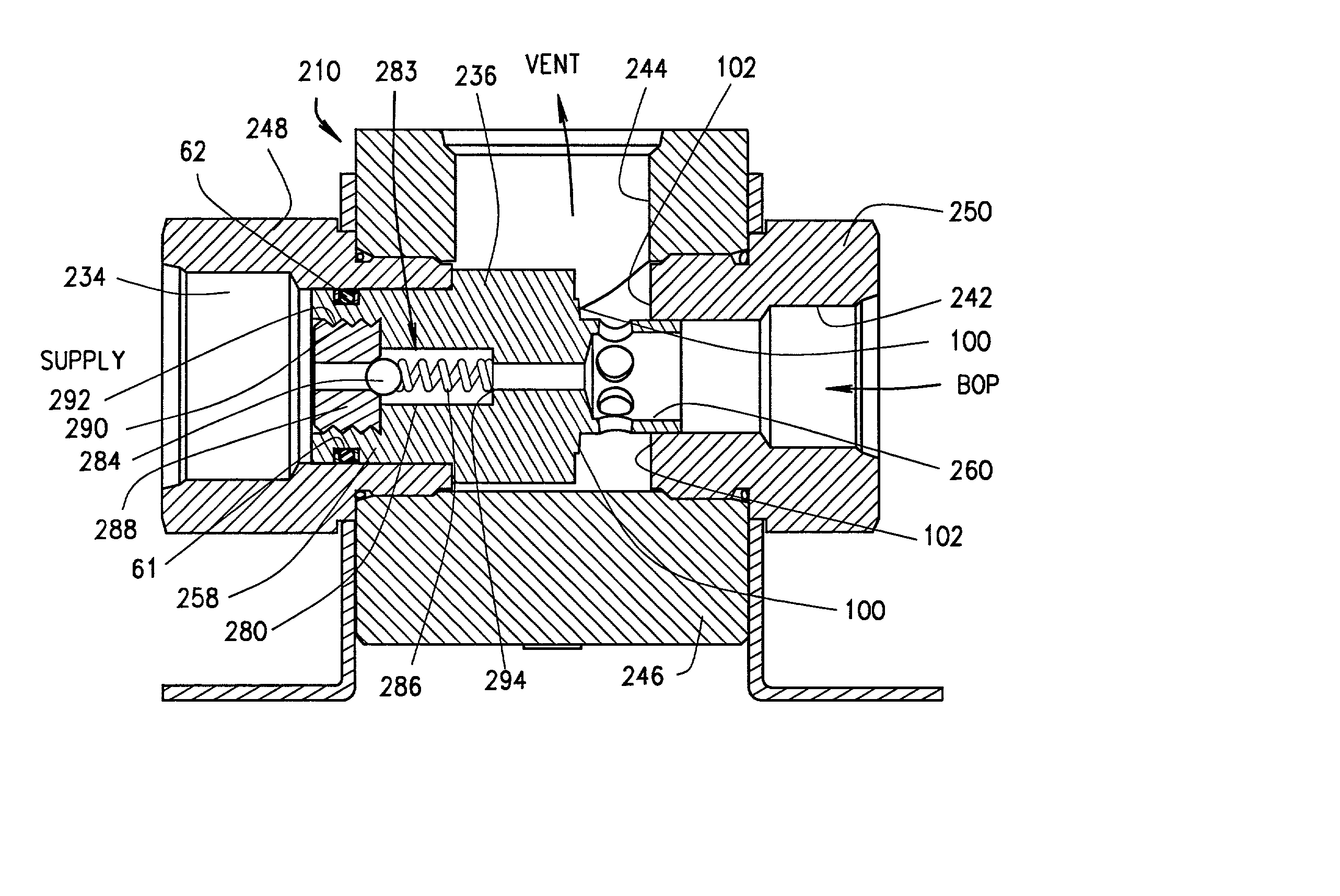
[0023] FIG. 4 is a section view of the quick dump valve of FIG. 3 in the vent position with flow arrows showing the direction of fluid flow from the BOP through the dump valve and out the vent.

[0024] FIG. 5 is a section view of the dump valve of FIG. 3 in the open position wit...


PUM


Abstract

In some prior art Blowout Preventer (BOP) operating systems, high velocity fluid flows and low differential pressures induced vibration in the system. This vibration may result in collapse and failure of hydraulic hoses in the system. A quick dump valve has been added at or near the open port on the BOP assembly to reduce vibration and other problems. The dump valve has a vent position and an open position. Several alternative embodiments add a ball check valve assembly to the shuttle in the quick dump valve.

Description

[0001] This application contains some common subject matter with U.S. Provisional Application Serial No. 60 / 265,444. As to this common subject matter, Applicants claim benefit of the provisional patent application filed on Jan. 31, 2001, Serial No. 60 / 265,444.[0002] 1. Field of the Invention[0003] Drilling rigs use blowout preventers (BOPs) to shut in a well during emergencies and for other purposes. The BOP operating system needs to be reliable in order to protect lives, the environment, and property. This invention relates to an improved BOP operating system and a quick dump valve. The quick dump valve includes a shuttle that has some structural similarity to shuttle valves used for control functions in prior art BOP operating systems. Specifically, the quick dump valve has some structural similarities to the Low Interflow Hydraulic Shuttle Valve which is the subject of a pending U.S. patent application Ser. No. 09 / 452,594 filed on Dec. 1, 1999 and a pending U.S. patent applicatio...

Claims


Application Information

Patent Timeline
Patent Type & Authority Applications(United States)
IPC IPC(8): E21B3/06E21B34/02
CPCE21B3/06E21B34/02E21B33/06E21B34/16Y10T137/7841Y10T137/2567Y10T137/2544E21B34/04
Inventor HOLLISTER, F. HAROLDCURTISS, JASON P. IIISPRINGETT, FRANK B.
Owner PROSERV GILMORE VALVE LLC
Why Eureka
Try Eureka